thank you for this advice. "photobucket" and "imageshack" are not helpful without high speed web access like in my village."This URL don't goes open. is this the same than the upload from post #3 about this thread? - "
All three are the same, and all three worked for me.
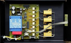
Interesting observations. The reason therefore are clearly find out by measuring voltage and current flow at the same time like the diagrams from post 39 here on this thread - go toThanks for all the pointers. I have been putting up with a lot of transformer hum. I built the circuit referenced in this site. It is in my power distribution box serving 2 large OTL tube amps and a music server.
Mains DC and Transformers
I used 2 big electrolytic caps.. 30v 12,000 uf. They have 8A ripple current.
The initial results were terrible. Much more humming from all the torroids. It sounded like they were being overloaded. I felt it possible they were starving for sufficient current.
I added 2 more caps. MUCH better but still some hum.
Added 2 more caps. Now 3 pairs of series caps with a total of 72mf. All hum from all transformers gone.
The biggest change was much improved dynamics and sound quality. Clearly ridding the transformer saturation was a good thing for the sound.
http://www.diyaudio.com/forums/powe...buzzing-toroid-transformers-what-right-4.html
Last edited:
is this the part I was not reading/understanding?but as I said the core also has integrating properties.
If the core is acting as the integrator, then it is that integrating function of the core that ADDS up the imbalance of the wave to wave flux until the reactive impedance of that flux can't resist the primary voltage as well and excess current flows around the primary.
Does that correctly explain it?
BMW850 prefer the circuit from post 159 about this thread:No need for fast/soft recovery in this application. Ideally they almost never conduct. Just use reliable high-current bridge rectifiers.
Cheers,
Bob
http://www.diyaudio.com/forums/solid-state/2080-dc-filter-16.html
the circuit description is here on his own website:
DC-Blocker - Scintilla-buizenversterkers
This circuit isn't to realize with a bridge rectifier, only with single diodes. Each electrolytic capacitor get its own diode.
What are the advantages in opposite to the most used topology as shown in Rod Elliott's schematic in fig. 3 ?? - go to
Mains DC and Transformers
Thank you for advices.
P.S. concerning DC filter here and on other portals are a lot of threads. To find the most interesting posts, go to
http://www.diyaudio.com/forums/soli...oidals-summary-most-interesting-comments.html
Last edited:
Yes, and because you can build a high-pass filter with a capacitor and a resistor, OR with a resistor and an inductor, you can use the primary/core itself as its own DC-reject element, but you have to protect it at the same time, which calls for non-linear elements as the R part.If the core is acting as the integrator, then it is that integrating function of the core that ADDS up the imbalance of the wave to wave flux until the reactive impedance of that flux can't resist the primary voltage as well and excess current flows around the primary.
Does that correctly explain it?
The properties of the core are especially valuable in this role: it isn't simply a linear inductor, it is a swinging inductor that will reduce its inductance (and raise the corner frequency) when the DC component increases.
It thus makes an adaptative filter, and unlike the C-type, it doesn't have resonant frequencies between C and the magnetizing or leakage inductances.
If it is associated with the C-filter, it will damp resonances if they become too large in amplitude
Any news in this matter?No, I don't think this regarded your posts - in the attachement I summarize it a bit.
I'm trying as I can replicate in my simulation program (Circuitmaker) different conditions from the mains (parasitics like unwanted dc components through rectifiers for half power mode). If I have success, then I can investigate exactly all mains DC filter topologies.
Who knows about modelling of toroidal transformers, especially the behaviour variations of different materials of the core? I want an equivalent circuit network of resistors, capacitors and inductors therefore.
Hello, Ive just read the whole of this thread as i too have a humming torroid.
I have just run some experiments using a signal generator and the ESP circuit and hooked up a transformer so theres a load. Without the load (yes, i tried this first....) it didnt work at all. The output mirrored the input. This was all low voltage/low current as i wanted to have a play and see what was happening. I dont think this is an answer but may shed some light on the diode only circuit. Apologies to those who already know all about this and if it seems obvious. Ive found something i didnt expect and thought id share it....
With the capacitors the circuit works beautifully. Takes a few seconds to stabilise but was able to remove a large dc component. (as much of an offset that my el cheapo signal generator could give before the signal clips on its rails).
Without the caps the diodes did distort the output sine wave, gradually improving until the offset became about more than 1.1v or so at which point the output was clean and offset free.
At 1v pkpk input the distortion was massive but at 5v there was essentially a sine wave although the peaks were distorted but was proportionately less. I wonder if at full mains swing this distortion (in the eyes of crown) is considered negligable and reducing possible dc offset is considered preferable. Would this distortion be filtered out in the dc rectification smoothing caps?
I tried adding the second set of diodes and it reduced the distortion a tiny bit but nothing to write home about.
Best way to avoid hum is the use of the right transformer like Plitron - go to
Measuring Acoustic Noise Emitted by Power Transformers
But in the case of existing amp devices this is often too expensive.
There are a lot of threads to this topic - go to
DC Filter against humming Toroidals - Summary of the most interesting Comments
Post #159 under
dc filter
is the royal way from my view, as long as parts used which are adequately dimensioned.
AndrewT (post #161) don't think so.
Maybe this device is still better (go also to the attachment):
http://www.horch-gmbh.de/Produkte/Line Silencer.pdf
What is currently the best solution for implementing a DC filter in exist amps with humming toroidal transformer ?
Attachments
Last edited:
Who knows this DC blocker:
http://www.horch-gmbh.de/Produkte/Line Silencer.pdf
Unfortunately there is no english description available - here my try of translation of the essentials :
German:
.............
In diesem Fall schafft der HORCH Line Silencer Abhilfe! Er mißt die störende Gleichspan-
nung und neutralisiert sie. Besonderheiten des Line-Silencer hierbei sind, daß die Zeitkon-
stante des PI-Reglers auf das Driftverhalten von Transformatorkernen abgestimmt ist.
Unter Einbezug des eigenen EMV-Meßplatzes in die Entwicklung, ist es gelungen , eventuell
von dem Gerät selbst ausgehende Störungen völlig zu eleminieren. Dadurch ist gewährleistet
daß vom Line-Silencer keinerlei nachteilige Wirkung ausgehen kann!
Die Funktion des Line-Silencers wird durch Leuchtdioden angezeigt:
Gelbe LED´s : +DC / -DC: zeigt die Polarität der Gleichspannung.
Rote LED: Der Line-Silencer kompensiert aktiv.
Grüne LED : Der Gleichspannungswert ist noch so niedrig, daß keine Maßnahme erforderlich ist (ca. ±5mV).
==================================================================================
English:
.............
In this case the HORCH Line Silencer provide the appropriate solution.
It measures the unwanted DC voltage components and compensate them.
A very special feature of the Line Silencers is follow:
The time constant of the PI controller unit is adjust to the drift behavior of transformer cores (this I don't understand).
With respect of the own EMV measuring station in the concept, it has succeeded to eleminate possibility interference completely outgoing from the device itself (this I also don't understand).
This ensures, that can come from the line silencers no adverse effect!
The function of the Line Silencers is indicated by LEDs:
Yellow LED's: + DC / DC: indicates the polarity of the DC.
Red LED: The Line-compensated active silencers.
Green LED: The DC value is so low that no counterstep is necessary (approximately ± 5 mV).
Please note - since I don't even understand in German, the quality of English translation is of course questionable.
Perhaps one of the members can post a schematic of this device.
In this case this interview with the German developer is of interest:
Interview mit einem Audioentwickler (vorsicht lang!!!, 24 kB)
or
Google Groups
I have a question, how would DC get onto the mains line in the first place?
As I found out, using a solid state relay to sequence on the amp will cause a huge imbalance and buzz.
 )
)yes, here are examples:
L C Audio Technology / DC Filter
DC filter — Audio Chews
Combined Module DC Blocker & EMI/RFI/Common Mode Filter - Assembled & tested PCB | eBay
http://www.sedlbauer.de/media/dc-netzfilter-250v-10a_313141_deutsch.pdf
DC-Filter, Gleichspannungs-Filter, Netzfilter, 230V, Hifi, Audio
A major disadvantage of all commercial units, however, is the loss of dynamism while listening tests (mostly by the use of big toroidal transformers with 1KVA and more). The reason are too small electrolytic capacitors with a small cv product (without screw terminals), i. e. very high capacity and very small outline at the same time.
I am still looking for the schematic of the unit in post #61 - go to
Variations of DC Main Filter against buzzing Toroid Transformers - what is the right?
because this approach is very different (without any loss of dynamism).
Last edited:
...appropriate diode technology for this? ...
The caps do the blocking.
The rectifiers just limit the over-voltage on the caps so the do not go BOOM if something goes wrong. Use standard Si parts. Low-threshold parts will spoil the capacitor blocking.
what happens, if I remove the diodes and replace the electrolytic caps by non polar versions ? like those under
file:///C:/Users/admin/Downloads/technical_file_LNK-P5Y-8000-80.pdf
or
file:///C:/Users/admin/Downloads/technical_file_LNK-M3_1-4700-70%20_.pdf
found under
DC Link Power Capacitors Archivi - ICAR
Overview resp. line-up from ICAR:
https://www.amelec.ch/infocenter_icar.html?file=tl_files/amelec/downloads/icar/LNK_2016.pdf
Actually the best solution - isn't it ?
Dc blocking circuit (developed and implemented in the 60s) works very well and I have been using it for many years, since the 90s. When it comes to "dynamic reduction" i wolud say it depends on what you are looking at. It´s not that simple.
The buzzing sound from a transformer is reducing the s/n ratio quite dramatically and can be annoying. A DC blocker fix that!
If you think that the voltage drop of 1 volt out of 230volt will cause a dynamic reduction electrically i would say no. Unless you have a zero feedback design. Otherwise with a small amount of negative feedback the difference in power supply voltage is not affecting the music signal at all. IF your amplifier is that sensitive for power supply voltage, that a small supply voltage change is noticeable in sound reproduction, simply change amplifier!
- Home
- Amplifiers
- Power Supplies
- Variations of DC Main Filter against buzzing Toroid Transformers - what is the right?