there is another thread running at the moment trying to get answers on this. So far no one has come out to confirm if the Disconnecting Network (which has been proved to pass Fault Current) is allowed between Chassis and Protective Earth.Am I correct in assuming that Bryston still bolts the safety ground to the chassis, and that that is the only place where the chassis is connected? Am I correct in assuming that a non-direct connection of safety ground to chassis (as through the diode arrangement) would never be allowed?
there is another thread running at the moment trying to get answers on this.
Where? Here on diyaudio?
"Am I correct in assuming that Bryston still bolts the safety ground to the chassis, and that that is the only place where the chassis is connected? Am I correct in assuming that a non-direct connection of safety ground to chassis (as through the diode arrangement) would never be allowed?"
Yes, you are correct. The ground wire from the IEC goes to the chassis, the the diode arrangement is between chassis ground and the central audio ground.
Yes, you are correct. The ground wire from the IEC goes to the chassis, the the diode arrangement is between chassis ground and the central audio ground.
"Am I correct in assuming that Bryston still bolts the safety ground to the chassis, and that that is the only place where the chassis is connected? Am I correct in assuming that a non-direct connection of safety ground to chassis (as through the diode arrangement) would never be allowed?"
Yes, you are correct. The ground wire from the IEC goes to the chassis, the the diode arrangement is between chassis ground and the central audio ground.
Thanks!
BTW, I think there is another issue that pertains to the Crown implementation of the DC blocker. Without the caps that Bryston uses, the diodes in the bridge will switch at the mains rate, just like diodes in the rectifier bridge in the secondary circuit. For this reason, I believe two rectifier snubber resistors should be used in the Crown arrangement. One might even argue that those bridges should be fast-recovery for the same reason the ones on the secondary side want to be. The Bryston arrangement does not have this issue because the diodes never conduct under normal conditions.
In the Bryston implementation, the electrolytic capacitors should have very low ESR and be rated for high ripple current. Moreover, that arrangement should probably not be used for amplifiers that do not incorporate a soft-start circuit. Otherwise the capacitors will be subjected to harsh turn-on current transients.
Cheers,
Bob
if capacitive reactance+ESR*I is greater than two diode Vdrops, the diodes start to bypass the capacitors during start up and maybe during periods of mild overload.The Bryston arrangement does not have this issue because the diodes never conduct under normal conditions.
......... not be used for amplifiers that do not incorporate a soft-start circuit. Otherwise the capacitors will be subjected to harsh turn-on current transients.
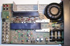
I like the Bryston circuit, and am particularly interested in the left side, where the safety ground from the line cord is connected to the main circuit ground through a resistor shunted by the bridge arrangement. I have done the same thing before in an amplifier for my own use, but was never sure if this approach would pass muster for a commercial product. If I understand the operation correctly, the resistance breaks ground loops that may occur among the safety grounds of interconnected equipment. The diode still provides safety ground protection by never allowing the circuit ground to differ from the safety ground (in a fault condition, for example) by more than 1.4V. This is why a large bridge device is presumably used. I am a little surprized that they used a resistor as large as 100 ohms. I used less than 10 ohms in my arrangement, which I think would be plenty to effectively break the ground while still maintaining a reasonably low impedance back to the safety ground.
Am I correct in assuming that Bryston still bolts the safety ground to the chassis, and that that is the only place where the chassis is connected? Am I correct in assuming that a non-direct connection of safety ground to chassis (as through the diode arrangement) would never be allowed?
Cheers,
Bob
Hallo Bob,
today I get a "Cyrus II" from Mission for checking. After opening I found a burnt/destroyed resistor and a capacitor, which must be exploded. I replace this components for the third time (and much more bigger versions than the original purchases). But I think, in one or two years the same work is necessary again.
This devices are also arranged between the safety ground from the line cord and the main circuit ground, but not shunted by an diode network (bridge arrangement - as you it call) like Bryston. But this could be the right solution also in case of the Cyrus II.
Nevertheless - for me it would be interesting to know, from where comes such large voltage/current transients between these two ground potentials?
Perhaps it must have to do with temporarily, very rare and very short but very large different earth potentials between Broadband-Cable connection for radio and TV and that one from mains voltage connection.
Last edited:
is CyrusII double insulated or does it have a protective earth wire connected to chassis?
The versions for the German marked have a protective earth wire connected to chassis (also by Cyrus ONE/I/1. But I don't know exactly, what about the other countries. In German the mains voltage connector haven't a polarity, i. e. I can pull out the wall connector, turn around and plug in in this second polarity (please note: only by the wall connection, but not by the amplifier main connections). In your country this isn't possible.
For this reason you will not find the RC network at the PCB from attachement (british version - I think), not even the PCB hole therefore.
By German versions this network is to find in line of the PCB GND wire from the electrolytic crosspoint (right of the screw, that is close by the volume control potentiometer). One end is solder to this mentioned PCB wire (electrical GND) and the other is connected to the screw (chassis GND).
Attachments
Last edited:
if capacitive reactance+ESR*I is greater than two diode Vdrops, the diodes start to bypass the capacitors during start up and maybe during periods of mild overload.
This is correct, but the soft start reduces the incidence of stress on those capacitors. During the magnetization pulse for a large toroid power transformer the current can be very, very high, and the bridge diode drops may go as high as 1.3V or more each, placing perhaps 2.6V of reverse voltage on one of the electrolytics.
Cheers,
Bob
Are devices for 50A continuous flow enough (steady state or stedy state current - I don't know the english term) ?
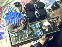
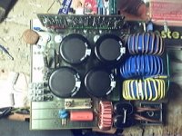
Here my circuit idea for all cases, where it is possible to insert the mains plug for the wall connection also in the other way. If there are DC >800mV, the right way for plug now is clearly find out. The proposal value of 20mF (20000 uF/100V) must be a computer grade version with lowest possible ESR (e. g. RIFA/EVOX or FTcap). Together with bypass of 100uF MKP for motor run I don't expect problems. For the diodes perhaps high speed versions with more peak current could be provide additional values of realibility.
Attachments
Last edited:
unequal current draw from the +ve halfwaves from the -ve halfwaves.
It's how all the SMPS are built.
They halfwave rectify and charge a cap to ~400Vdc. If they all came from the same manufacturer they would all draw from the same halfwave.
SMPS all use full wave rectifiers.... They have to, to prevent the situation you are talking about, and to limit peak diode current.
You wont EVER see a SMPS with a half wave rectifier, so you are incorrect about that.
Google image search agrees with me here.
http://www.optimus-power.com/images/Smps.gif
Note the full wave rectifier.
Here is another one:
http://www.smps.us/power-supply.html
Another one:
http://freecircuitdiagram.com/wp-content/uploads/2009/07/constant-voltage-smps-circuit.gif
And the actual diagram for a standard computer power supply.
http://www.pavouk.org/hw/en_atxps.html
Last edited:
unequal current draw from the +ve halfwaves from the -ve halfwaves.
It's how all the SMPS are built.
They halfwave rectify and charge a cap to ~400Vdc. If they all came from the same manufacturer they would all draw from the same halfwave.
Andrew,
I certainly don't claim to be an expert on the innards of switching power supplies, but if what you say is true (and I am understanding correctly), I am shocked (aaahhh, poor choice of words). Why on Earth would the front end of a switching power supply not use a full-wave bridge to charge the input capacitor and power the supply?
Cheers,
Bob
I agree. Not finding a bridge rectifier or 4 diodes at the hot end of a mains SMPS is just wrong, and extremely bad design.
The switch on current with a bridge is bad enough, i would imagine half wave would be shocking. You wouldnt use a thermistor as a continuous surge protection, it would burn itself into a crisp.
Every single mains SMPS i have every yanked apart, mainly computer ones, use a bridge, or worst case, four discrete diodes.
Any thermistor you see in a TV smps will be for the deguass coil. There is a class of thermal device designed for the inrush current of a large smps, but its not technically a thermistor, its more a class of MOV.
Any thermister you see in a TV smps is designed to allow full current immediately, then as it warms up, limits current to a very low value, thus, creating a deguassing effect with a large aluminium or copper coil around the picture tube.
Thats the "dong" you hear when you plug in some tvs/monitors.
Finding DC on the mains would be terribly rare. Any inductive device across the mains would instantly remove the DC component, which includes any transformer or inductive motor.
Transformer hum isnt caused by a dc component, its caused by a non sine non symmetrical wave being placed across the mains lines, or a loose wire/lamination. The most common cause of that is very large industrial equipment.
The absolute best way to help remove unwanted signals from the mains is with a power conditioner, which really is just a 1:1 transformer, usually with taps at say 1:1.1, 1:1.05, 1:1, 1:0.95 and 1:0.9 with a automatic switching using triacs to maintain line voltage.
The transformer in power conditioners is usually massive and designed to be resonant at the mains frequency, perfectly idea for remove any possible DC from the line, as well as cleaning up the waveform and helping remove a lot of noise from the line.
As a bonus, a basic 1:1 isolation transformer is also the perfect way to remove earth loops.
Putting any form of non linear device in your mains line, be it bridges or even large electrolytic capacitors is a recipe for actually ADDING noise and non linearity to your mains supply for your amplifer.
In this forum, its a popular opinion to remove caps from paths to help increase the quality of sound, and here in this thread, there is a consensus for adding non linear devices like diodes and caps TO the design in the name of increasing quality of sound.
Bit of a logical hole there somewhere.
You want your toroid/transformer to be fed with the cleanest sine wave possible, with no DC offset, which is a rather rare occurance anyway, especially if you have a fridge or flourescent light, feed it with a nice clean sine wave from a ferro resonant power conditioner.
Last edited:
unequal current draw from the +ve halfwaves from the -ve halfwaves.
It's how all the SMPS are built.
They halfwave rectify and charge a cap to ~400Vdc. If they all came from the same manufacturer they would all draw from the same halfwave.
You are not right, SMPS are built the opposite, for symmetrical current draw. Now I can be considered a commercial SMPS designer, so I suppose I have some authority to say that. I have only seen half wave rectification in ultra low cost switchmode battery chargers or small wall warts, all below 5W.
Conventional SMPS full wave rectify 220V-240V AC to 310-340V DC, or use a voltage doubler on 120V AC to get 340V DC. Newer SMPS use active Power Factor Correction, which simulates a resistive load on mains line through a full bridge rectifier, sometimes with as low as 1% THD, and outputs approx. 400V DC with slow regulation. You probably understood the circuit the wrong way when you looked inside the SMPS appliances you mention.
However, I have seen half wave rectification used to allow half power operation in old appliances like space heaters, hair driers, soldering irons, etc... I own a 1500W space heater from early 1980s that also does 750W through a 1N5407 diode. When I turn it on at half power, toroids start to buzz.
I believe this is no longer allowed by safety regulations.
Note that in most parts of the world mains plugs have no polarity (unlike in UK), including Europe, so when using those troublesome appliances, chances from drawing more current in one direction or in the other are mostly random and the DC offset should ideally tend to be cancelled.
To Rainwulf:
I did many tests some years ago concerning DC offset on mains line and buzzing toroids. Distorted waveforms can make a transformer produce some noise when they have strong high frequency components, but DC on mains line results in far more noise due to transformer saturation, which manifests itself as sharp high current peaks just before voltage crosses zero.
Last edited:
First image is current (red) and voltage (blue) in a 750VA toroid with the usual DC offset at my place, .2A/div and 100V/div. Little audible noise.
Second image is current and voltage when I turn on the 1500W heater in half power mode, 2A/div and 100V/div. Note the huge current peaks due to saturation. Big audible noise.
Third image is current and voltage when a simple DC filter is added (1000uF and 2 back to back diodes), .02A/div and 100V/div. Transformer becomes completely quiet, even with the heater in half power mode.
Attachments
And these waveforms are from a 3KW active PFC prototype that I did a long time ago. They were obtained while simulating low line conditions, blue trace is input voltage at 50V/div, red trace is input current at approx. 10A/div (working at over 2KW).
Note how well the current waveform tracks the voltage waveform. The slight phase lead in current waveform is because several microfarads are required in parallel with the input to filter EMI properly.
Note how well the current waveform tracks the voltage waveform. The slight phase lead in current waveform is because several microfarads are required in parallel with the input to filter EMI properly.
Attachments
- Home
- Amplifiers
- Power Supplies
- Variations of DC Main Filter against buzzing Toroid Transformers - what is the right?