check out this thread:I’m still waiting for someone to show what DC on a the mains looks like with a scope.
DC Filter against humming Toroidals - Summary of the most interesting Comments
what different in general there is between the older and the currently version from LC technology ?
1) L C Audio Technology / DC Filter
2) L C Audio Technology / DC Filter
Thank you for this information.
1) L C Audio Technology / DC Filter
2) L C Audio Technology / DC Filter
Thank you for this information.
The trick is to look at the AC mains current waveform consumed by a toroidal transformer primary winding - if it is symmetric then there is no dc bias influencing the core - if it is not symmetric then there is some net dc current shifting the BH curve loci.I’m still waiting for someone to show what DC on a the mains looks like with a scope.
The voltage drop of the diodes isn't critical in order to audible dynamic loss.Dc blocking circuit (developed and implemented in the 60s) works very well and I have been using it for many years, since the 90s. When it comes to "dynamic reduction" i wolud say it depends on what you are looking at. It´s not that simple.
The buzzing sound from a transformer is reducing the s/n ratio quite dramatically and can be annoying. A DC blocker fix that!
If you think that the voltage drop of 1 volt out of 230volt will cause a dynamic reduction electrically i would say no. Unless you have a zero feedback design. Otherwise with a small amount of negative feedback the difference in power supply voltage is not affecting the music signal at all. IF your amplifier is that sensitive for power supply voltage, that a small supply voltage change is noticeable in sound reproduction, simply change amplifier!
But the effect by low voltage capacitors (6V, 10V, 16V or 25V) is really not to be neglected due to the absence of low ESR character.
My favorite topology for a DC filter you will find under
DC-Blocker - Scintilla-buizenversterkers
and I use 47.000uF electrolytic caps.
Listening tests both with lower voltages below 25 VDC and 63VDC so as 100VDC in very big cans provided a clear result (this was tested on the X250 by Pass Labs - check the images in post #19+20 under
Pass X250 repair
in case of the used toroidal transformer)
check out the interview between reviewer for The Absolute Sound and Mr. James Bongiorno, developer for SAE, SUMO and some other company - go to
https://www.diyaudio.com/forums/pow...bar-mains-dc-mains-voltage-2.html#post6455330
https://www.diyaudio.com/forums/pow...bar-mains-dc-mains-voltage-2.html#post6455330
according the description under
Direct Current Blocker AUDIOLAB DC-BLOCK - Horn Online Shop
a typical RF filter like this one under
Netzfilter, HiFi Entstorfilter von THEL, audiophile Netzzentralen selber bauen | Hifi, Selber bauen elektronik, Filter
and a DC Filter similar to this one:
https://www.atlhifi.com/wp-content/uploads/2019/08/DC-Blocker-2.3-print.png
an internal image is necessary to create a circuit diagram more exact.
DC Blocker Trap Filter – Assembled in Case – v.3 – ATL Audio Ltd.
Last edited:
This seems to be an interesting approach (new for me):
DC-Filter, Gleichspannungs-Filter, Netzfilter, 230V, Hifi, Audio
unfortunately only described in German language.
DC-Filter, Gleichspannungs-Filter, Netzfilter, 230V, Hifi, Audio
unfortunately only described in German language.
I am looking for a schematic for a friend. He want to clone this shunt controlled DC filter unit - here a good description from NL:Who knows this DC blocker:
http://www.horch-gmbh.de/Produkte/Line Silencer.pdf
Unfortunately there is no english description available - here my try of translation of the essentials :
German:
.............
In diesem Fall schafft der HORCH Line Silencer Abhilfe! Er mißt die störende Gleichspan-
nung und neutralisiert sie. Besonderheiten des Line-Silencer hierbei sind, daß die Zeitkon-
stante des PI-Reglers auf das Driftverhalten von Transformatorkernen abgestimmt ist.
Unter Einbezug des eigenen EMV-Meßplatzes in die Entwicklung, ist es gelungen , eventuell
von dem Gerät selbst ausgehende Störungen völlig zu eleminieren. Dadurch ist gewährleistet
daß vom Line-Silencer keinerlei nachteilige Wirkung ausgehen kann!
Die Funktion des Line-Silencers wird durch Leuchtdioden angezeigt:
Gelbe LED´s : +DC / -DC: zeigt die Polarität der Gleichspannung.
Rote LED: Der Line-Silencer kompensiert aktiv.
Grüne LED : Der Gleichspannungswert ist noch so niedrig, daß keine Maßnahme erforderlich ist (ca. ±5mV).
==================================================================================
English:
.............
In this case the HORCH Line Silencer provide the appropriate solution.
It measures the unwanted DC voltage components and compensate them.
A very special feature of the Line Silencers is follow:
The time constant of the PI controller unit is adjust to the drift behavior of transformer cores (this I don't understand).
With respect of the own EMV measuring station in the concept, it has succeeded to eleminate possibility interference completely outgoing from the device itself (this I also don't understand).
This ensures, that can come from the line silencers no adverse effect!
The function of the Line Silencers is indicated by LEDs:
Yellow LED's: + DC / DC: indicates the polarity of the DC.
Red LED: The Line-compensated active silencers.
Green LED: The DC value is so low that no counterstep is necessary (approximately ± 5 mV).
Please note - since I don't even understand in German, the quality of English translation is of course questionable.
Perhaps one of the members can post a schematic of this device.
https://audio-creative.nl/recensie-2/horch-line-silencer/3/According the image under
https://audio-creative.nl/wp-content/uploads/Horch-Line-Silencer-binnenkant.jpgthere are in use 8 optocoupler, a mini dip (dip-8), a 18 pin dual inline IC and a reed relais - all mentioned parts without type No.
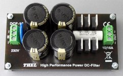
Most commercial available DC-Blocker as accessory unit do not pay attention to this important fact - go to image one of attachment. Image two and the unit (from post #270) underThanks!
The Bryston arrangement does not have this issue because the diodes never conduct under normal conditions.
In the Bryston implementation, the electrolytic capacitors should have very low ESR and be rated for high ripple current.
Moreover, that arrangement should probably not be used for amplifiers that do not incorporate a soft-start circuit.
Otherwise the capacitors will be subjected to harsh turn-on current transients.
Cheers,
Bob
https://www.diyaudio.com/community/...lter-for-toroidal-transformers.317094/page-14
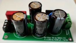
looks slightly better, but still not sufficiently low ESR.
Consequence concerning sonic character of power amp is, that loss of dynamics must be accepted during listening tests (and of course the risk of destroyed components).
Therefore I am looking for a commercial available DC-Blocker with electrolytics from top class (go to image three, four and five from my attachment) - unfortunately no supplier I have found until this day - so it is necessary to realize a suited diy project for this.
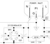
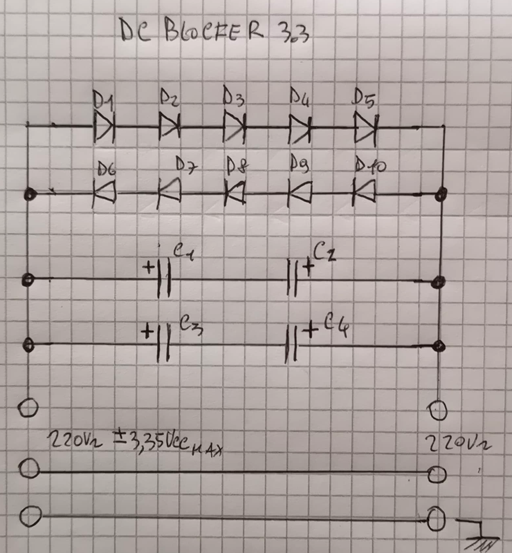
But here rises up the question, what are the pros and cons of each approach from circuit diagram of image six - go also to
https://scintilla-buizenversterkers.nl/scintilla-buizenversterkers/zelfbouw/zelfbouw sites/DC-Blocker.htm
and image seven (most used circuit topology - first time I have found in Bryston amp devices).
Maybe you have an idea.
Attachments
-
 DC-Blocker.jpg109.1 KB · Views: 56
 -
 DCF-10.jpg155.5 KB · Views: 47
 -
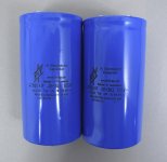 47mF-100V FTcap GM Series.jpg268.3 KB · Views: 47
 -
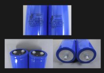 47mF-100V FTcap GM Series-II.jpg150.8 KB · Views: 45
 -
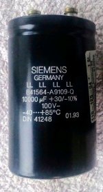 10mF-100V Siemens LL series.jpg67.9 KB · Views: 56
 -
 DC Blocker.gif8.2 KB · Views: 69
 -
 Bryston 4B SST extract.png10.5 KB · Views: 61
Last edited:
Good evening.
Yesterday I made these circuits for my power amp with 2 500VA Toroidal that would occasionally emit an audible hum up to three meters, even just after powering up.
Apparently this noise has been greatly reduced with the circuit I made using only two 47000uF capacitors I oridinate two more to be connected in parallel.

- Home
- Amplifiers
- Power Supplies
- Variations of DC Main Filter against buzzing Toroid Transformers - what is the right?