since when power is anything but scale up of something else?
And btw, there is no such thing as continous if you make it for audio")
You are pointing for somthing else, It is for audio.
But in order to get a professional SMPS, you must push it to the limits.
I cant build it to deliver 2.5KW, and say its 4KW PEAK, like Re***Au
How ever , every thing will be posted (Pictures) when it gets completed!
Regards Friend.
Maybe is not 4KW, so u have to connect serial heater that u will use like a resistor, to decrease powerThis is one funny topic.
Just because everyone needs 4KW at their stereo...
)) see yaNice transformer,
It looks like a FOIL wind, isn't it??
why do you think it is a foil wound?
microsim,
I can understand your pride at having finished winding your transformer.
However, consider things from our point of view - you post a photograph of a transformer with nothing before or after.
What are we supposed to do ? Say "well done son, I knew you could do it!" ?
Microsim's pride is OVERRATED!!
who let the dogz out
carefully inspect the bobbin, the bulge with wire winding is missing for tightly packed construction.
why do you think it is a foil wound?
carefully inspect the bobbin, the bulge with wire winding is missing for tightly packed construction.
Microsim's pride is OVERRATED!!
Friend.
Why dont you show us your 4KW SMPS model? and post it here?
Also it is foil windings,
4kw smps
Folks, I am starting a new project. I have been on this site for many years and have many successful 1kw+ power supplies under my belt.
I do not like to see the bashing on here. If someone post a photo you may ask for more info otherwise wait for further developments.
I am working on PFC (power factor correction) circuits for several uses. One of which is a big Tesla Coil. I will be glad to share as I go along. I recently had to run a 50 amp 240 volt circuit to my bench so I would have enough power available to do this work. My latest pfc circuit is running at 4kw constant with an output of 400 volts d.c.
A good source of parts are old large NETWORK power supplies. I have bought all I could find at the local recycling place. One of the best was a box 10 inches by four inches by two inches that has an output of 12 volts d.c. at 175 amps! Killer mosfets inside this baby! Reverse engineering to follow!
Hello
Can you share your 1KW SMPS?
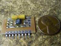
Here is the igbt driver board for my trial build. The little chip is an MIC4420. It is a single output rated at 6 amps into 10,000 pf. Might blow the traces off the board. I harvested it from an IBM power unit. There are seven more on the board yet.
Look up "Magnetics Inc" on the web, they have a nice tutorial on transformer design and the best part: There are charts with MAXIMUM POWER THROUGHPUT of all of their cores up to 26kw! TDK has some huge material available also. EE120, PQ120, and toroids up to about seven inches diameter.
Sch3matic, I am learning this to be used in three phase converters, my new Tesla coil, and I need to power a 480v three phase plasma cutter from 220v single phase. Internal supply (rectified 480) is 640vdc. Going to boost to about 620 and feed directly into the inverter. : ) If you see a mushroom cloud over Eastern Kansas, that WAS my house.
Attachments
SMPS reverse engineering.
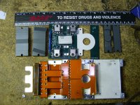
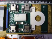
Here are some pics of an IBM supply I bought off of Ebay. A very neat piece of work. The main power board is an integral winding on a planar core. This supply put out 5.1 volts at 225 amps! The secondary is one turn of thick foil as seen in the picture. The power core is odd in that the "I" part is 3c85 material and the "E" part is N67 material. There is no gap in it.
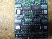
The gate drive transformers are planar as well with the windings being embedded in the board at each IGBT. The bridge is made of four MTW20N50 IGBTs. It was driven by MIC4420 driver chips and controlled by the board in the picture.
I am trying to get an understanding of these control chips, they do phase shifting with the two halves of the bridge as well as pwm. It operates in a current mode.
More to come as I have time and learn more.
Here are some pics of an IBM supply I bought off of Ebay. A very neat piece of work. The main power board is an integral winding on a planar core. This supply put out 5.1 volts at 225 amps!
The secondary is one turn of thick foil as seen in the picture. The power core is odd in that the "I" part is 3c85 material and the "E" part is N67 material. There is no gap in it. The gate drive transformers are planar as well with the windings being embedded in the board at each IGBT. The bridge is made of four MTW20N50 IGBTs. It was driven by MIC4420 driver chips and controlled by the board in the picture.
I am trying to get an understanding of these control chips, they do phase shifting with the two halves of the bridge as well as pwm. It operates in a current mode.
More to come as I have time and learn more.
Attachments
hello...
i made Luka's smps (with modifications on power stage) and drew 3kw from it. continuous power (3x1kw halogen lamps). so my guess is that Luka's design as it is found on diyaudio.com can easly go 1kw continuous.
i made Luka's smps (with modifications on power stage) and drew 3kw from it. continuous power (3x1kw halogen lamps). so my guess is that Luka's design as it is found on diyaudio.com can easly go 1kw continuous.
Okay
1KW model will be as DIY, not the 4KW model. still under design,
So take it easy on me people, if I knew this, I wont post that Eitehr!!
_LUKA_ your SMPS (posted over DIY) will blow up at 1000W continous test (I am sure), so thats an easy supply to make, we need REAL high power DIY SMPS,
Thanks All
hello...
i made Luka's smps (with modifications on power stage) and drew 3kw from it. continuous power (3x1kw halogen lamps). so my guess is that Luka's design as it is found on diyaudio.com can easly go 1kw continuous.
Hahahah
3Kw from LUKA power supply? I have no idea about that supply, but it will BLOW up, if you operate it AS IS.
If you made modifications, please show the Pictures, 3KW will make your 220VAC line suffer without PFC stage at 3KW load.
That circuit WILL handle 1KW or more, with proper heatsinks, and maybe a small fan.
One more thing, what transformer you have used to draw 3KW? since EE65 cannot support 3KW full Load. I wonder what you have done!
Bwahhahahha, you have no idea about it, yet you know it will blow, like BLOW...waaauuwww you must see future, or you have knowledge beyond our comprehension, since you see thing from schematicI have no idea about that supply, but it will BLOW up, if you operate it AS IS.
Please do tell, do tell what is wrong with it, hell if it can be better, I'd want to know that
Show us load
Dude,
Why dont you show a 1KW load connected to that supply, AS IS in the picture at your site, with thermometer attached to the heatsink, 5 hours connected to the load. Tell us results, and dont tell its 1KW, its dificult to prove that without pictures . or Scope signals at 1KW load
Also your design ARE not the end of this world in SMPS, you even dont know any other chip rather that IR2110 to drive Mosfets, IGBTs.
You are using 1000Uf capacitors at the input?, and its 1KW? I am using 4x2200UF to get that power dude, dont fool people. your SMPS is PEAK. wish to see scope signals at full load..
Also take it easy friend, its just discussion!
Bwahhahahha, you have no idea about it, yet you know it will blow, like BLOW...waaauuwww you must see future, or you have knowledge beyond our comprehension, since you see thing from schematic
Please do tell, do tell what is wrong with it, hell if it can be better, I'd want to know that
Dude,
Why dont you show a 1KW load connected to that supply, AS IS in the picture at your site, with thermometer attached to the heatsink, 5 hours connected to the load. Tell us results, and dont tell its 1KW, its dificult to prove that without pictures . or Scope signals at 1KW load
Also your design ARE not the end of this world in SMPS, you even dont know any other chip rather that IR2110 to drive Mosfets, IGBTs.
You are using 1000Uf capacitors at the input?, and its 1KW? I am using 4x2200UF to get that power dude, dont fool people. your SMPS is PEAK. wish to see scope signals at full load..
Also take it easy friend, its just discussion!
Last edited:
haha, it's too funny... just to start, I don't have to show you anything, I really don't care about your 5h tests, I don't even see one way that I wanted to use this smps, to operate 5h nor 5h at constant 1kw output.Dude,
Why dont you show a 1KW load connected to that supply, AS IS in the picture at your site, with thermometer attached to the heatsink, 5 hours connected to the load. Tell us results, and dont tell its 1KW, its dificult to prove that without pictures . or Scope signals at 1KW load
Also your design ARE not the end of this world in SMPS, you even dont know any other chip rather that IR2110 to drive Mosfets, IGBTs.
Also take it easy friend, its just discussion!
and yes, my gate drive option at the time of this build was only IR, that's just the way it was and its damn good IC, your problem if you don't like it
and you are the last one to tell anybody what is or it isn't, since you are all talk and no show, you post random thing that you say they are yours... well to make it short, you post your 5h test of your supply today, let us all see if you even have any design in construction
BTW, just coz you won't like it, (and yes my supply could be done better, but is as it is), I know few people already builded "my" supply and it works for them, and if they are happy with it, who am I or you to say, supply is not good, or it will blow?
There are very little things in the world that can't be improved, those that can be, does that mean they should/or must be?
and yes I always take it easy, even when I read your posts
Last edited:
- Status
- This old topic is closed. If you want to reopen this topic, contact a moderator using the "Report Post" button.
- Home
- Amplifiers
- Power Supplies
- 4KW EE65 Transformer