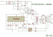
Hi, I found this schematic, it will work?
Please tell me what you think, thanks
At a quick glance, no.
You need to feedback both positive and negative rails independently.
Otherwise you could get 40v+50v=90v if rails take differing currents.
Ok
I am not Pro in SMPS
But:
1- I don't like the low voltage supply, that supplies the SG3525
2- Driving those Mosfets directly without IR2110, I don't think its good Idea!
3- Feed back loop needs some modifications
Also you can find better designs at diyaudio.com for such supply, that saves you time and money.
Best Wishes
You used PMOS type symbols, which wouldn't work so well in reality.
Gate charge isn't very big, so it won't switch too awful with 100 ohm gate resistors... you could drop those to 47 ohms pretty easily, the SG3525 will source/sink 200mA peaks easily enough. For higher efficiency and high frequency operation, gate drives would be a good idea.
The standby / oscillator supply is usually provided with a semi-regulated blocking oscillator, which takes another 10 parts or so plus transformer. This is usually justified by powering an external load as well (e.g. motherboard standby in an ATX power supply). This is quite a few more parts, but far more efficient than the big fat dropping transistor shown.
Tim
The power supply for the SG3525 is unreliable, there is nothing to limit inrush current when the capacitors after the IRF730 are discharged. This may destroy the IRF730 at startup from time to time.
A bias winding is missing too, and the linear supply for the SG3525 is only expected to provide some current at startup, until the circuit starts switching and the bias winding takes over. Using the startup supply continuously would result in too much heat produced in the pass transistor (IRF730).
To cause the bias winding to take over the startup supply, it's usually enough to use a linear regulator (fed from bias winding) whose output voltage is slightly higher (than startup supply output) and OR both outputs with diodes. Using a bipolar transistor for the startup supply may allow for better control of output voltage in order to get a more reliable take over process. That's because the Vbe of a silicon bipolar transistor is always around 0.6V (0.5V to 0.7V), but the Vgs of a MOSFET changes substantially with drain current and from part to part.
Also, note that this is a push-pull supply. The SG3525 will probably drive these MOSFET without additional buffers, but the drains are going to need snubbers or clamp circuits because, due to transformer leakage inductance, the drain voltage will rise in an uncontrolled way for some time at turn-off, which is likely to cause avalanche and destroy the MOSFET from time to time.
And finally, note that this is a 120V design, IRF840 are 500V parts, and you probably live in a 230V country. In push-pull circuits the switching transistors are exposed to two times the rectified input voltage plus some margin for inductive turn-off spikes. 1000V MOSFET would be required for 230V operation (400V+400V+200V, two times worst case peak mains voltage plus margin).
Last edited:
Can you sudgest a schematic?
Can you sudgest a schematic that don' t use IR215x family or hip 4080 (hard to find for me), is possible to make an all discrete smps or use the sg3525 or tl49x or uc384x to make such smps, and if possible without an external transformer to supply the low voltage for the ic.
Thanks all in advantage
Can you sudgest a schematic that don' t use IR215x family or hip 4080 (hard to find for me), is possible to make an all discrete smps or use the sg3525 or tl49x or uc384x to make such smps, and if possible without an external transformer to supply the low voltage for the ic.
Thanks all in advantage
Looks an awful lot like the thing posted in this thread, although this is an off-line switcher and the linked one is not, it shares several design features/flaws. Like in that design, I do wonder what the gate resistors are good for, the datasheet of the SG3525 clearly says you can do without them and use the shortest possible connections.
If you consider going on with this design, I would especially recommend taking Eva's comments very seriously. And please also discuss the layout here before you start putting something together. A schematic is a start, but remember that the layout is the only full description of the physical implementation. Many people post a schematic with the question if this or that will work. But in reality, a bad layout can totally screw up an otherwise good circuit. Consider the link above as an example of how things should not be done.
If you consider going on with this design, I would especially recommend taking Eva's comments very seriously. And please also discuss the layout here before you start putting something together. A schematic is a start, but remember that the layout is the only full description of the physical implementation. Many people post a schematic with the question if this or that will work. But in reality, a bad layout can totally screw up an otherwise good circuit. Consider the link above as an example of how things should not be done.
Last edited:
Part of the fun in DIYing is to start with something, find its flaws and make it better. With the suggestions everyone has given you, you actually have the opportunity to make your schematic better, by tackling one issue at a time. And if all works out well, we can start on the layout and the chances are actually pretty good that you'll end up with something that works.
So where do you want to start?
So where do you want to start?
Hi,
A few suggestions:
1) Change the SG3525 power supply section. It'd be best to use a small transformer or an auxilary bias winding.
2) Place a resistor between pins 5 and 7 of SG3525 to add some deadtime to prevent cross-conduction.
3) Reduce the value of the gate resistors. 100R will greatly increase switching losses and reduce efficiency. Instead use something like 10R or 22R.
4) Place bypass/decoupling caps from pins 13 and 15 of SG3525 to ground.
5) For safety, you could place a 1k resistor and 15v zener in parallel from gate to source of each MOSFET.
6) Add current limiting / short circuit protection circuitry.
7) Add an input fuse.
8) You don't really need 1H inductors at the input, instead try around 10-30mH.
9) Use snubbers/transient suppressor (transzorbs) across the transformer primaries.
10) With a 47uF softstart capacitor, your startup delay is greatly increased. Such a large delay may not be required. You can use 10-22uF instead.
11) Instead of IRF840, use MOSFETs with higher VDS like 800-900v.
12) Wind your transformer carefully.
I've made dozens of SMPS circuits, and have found these to be very critical in SMPS design.
Hope this helped.
Tahmid.
Hi,
A few suggestions:
1) Change the SG3525 power supply section. It'd be best to use a small transformer or an auxilary bias winding.
2) Place a resistor between pins 5 and 7 of SG3525 to add some deadtime to prevent cross-conduction.
3) Reduce the value of the gate resistors. 100R will greatly increase switching losses and reduce efficiency. Instead use something like 10R or 22R.
4) Place bypass/decoupling caps from pins 13 and 15 of SG3525 to ground.
5) For safety, you could place a 1k resistor and 15v zener in parallel from gate to source of each MOSFET.
6) Add current limiting / short circuit protection circuitry.
7) Add an input fuse.
8) You don't really need 1H inductors at the input, instead try around 10-30mH.
9) Use snubbers/transient suppressor (transzorbs) across the transformer primaries.
10) With a 47uF softstart capacitor, your startup delay is greatly increased. Such a large delay may not be required. You can use 10-22uF instead.
11) Instead of IRF840, use MOSFETs with higher VDS like 800-900v.
12) Wind your transformer carefully.
I've made dozens of SMPS circuits, and have found these to be very critical in SMPS design.
Hope this helped.
Tahmid.
Thank you a lot for the tips. I prefer to not to use a trasformer to supply the sg3525 but I'm newbie in AC swithing circuits, how to retreive the supply for the ic? Can you explain me? Thanks in advantage
Hi,
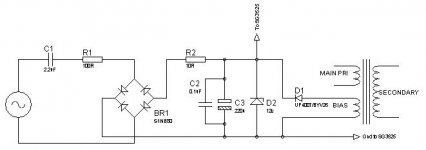
Okay, if you prefer not to use transformer, you should use bias winding then.
You'll have a power supply which in your circuit will act as a kind of 'starter' which will only supply current to the controller at power-up. Right after that your bias/auxilary winding will take over and supply the power.
Something like this could work.
Attachments
Ok, first thank you for the repos.... you told me that the schematic is not good. Can you propose another one? Based on ic like tl49x or similar?
I made a serch in internet but apart pc pws there' s not other, all suggestions will be good, thanks
Currently, the circuit needs a lot of modifications, but after that it should work fine. I have 2 offline power supplies using push-pull topology, one with ESBT and the other with MOSFET. Been working fine over a year and a half now.
Tahmid.
Hi,
Okay, if you prefer not to use transformer, you should use bias winding then.
You'll have a power supply which in your circuit will act as a kind of 'starter' which will only supply current to the controller at power-up. Right after that your bias/auxilary winding will take over and supply the power.
Something like this could work.
I think it will work.... changing polarity of rectification diodes
 , right?
- Status
- This old topic is closed. If you want to reopen this topic, contact a moderator using the "Report Post" button.
- Home
- Amplifiers
- Power Supplies
- Will this work? Please check