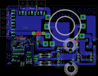
Those ancient IRFP064 waste a lot of space and don't perform that good. Newer TO-220 MOSFET will use less space and provide lower Rds-on. See IRF3205 or IRF2907Z for example.
A standard recovery diode bridge won't be up to the job either, too much reverse recovery charge is stored in that kind of diodes.
The push-pull layout is not good, current sharing between the triplets of MOSFET is not going to be good, and balancing between both banks isn't going to be good either, parasitic PCB resistances and inductances from each MOSFET to the transformer are quite different.
Input EMI filtering is missing, and the placement of the 6800uF 16V capacitor is far from optimum too.
Consider redoing the layout with double sided PCB and ground plane.
Last edited:
If you say that it works perfectly... 
How did you manage to get the CE approval?
To Tim: There is nothing wrong with having capacitors just after the diodes at the output, it just requires soft start, then transformer leakage inductance and capacitor ESR shape the current pulses nicely, and believe it or not, maximum current happens only at the end of the pulses, they are inverse-exponential (log) shaped, like in a LR lowpass filter.
Last edited:
If you say that it works perfectly...
How did you manage to get the CE approval?
To Tim: There is nothing wrong with having capacitors just after the diodes at the output, it just requires soft start, then transformer leakage inductance and capacitor ESR shape the current pulses nicely, and believe it or not, maximum current happens only at the end of the pulses, they are inverse-exponential (log) shaped, like in a LR lowpass filter.
What happens if input voltage rises by 10%?
Oops...
not an issue then dangerous and should not exceed max 13 volt
Your able to push 60+ AMPS through those traces?? Did you do anything to beef them up? Are you sure your pushing 800+ Watts?
What happens if input voltage rises by 10%?
Oops...
What happens to the big input capacitors if input rises by 10% suddenly?
A big current surge is required to do that, and since transformer leakage inductance is in series with secondary side capacitors, acting as a LPF, most of the surge current will flow through primary side capacitors.
Add a L in series at the input to complete the LCLC (LRCR LRCR) system and a sudden rise or fall on input voltage won't cause any current surge.
I see friends that at the circuit I'm using now and the entry of a car battery when I connect from the output (output 115 volt dc) 7 ampere output current I took the ultra fast diode (8x UF 5408) current circuit providing seamless access to the power supply when the fluctuation level of 5% does not yield the SMPS rate of 92% measurement has been tested me this circuit test a week from now on I had a problem trying pcb design and pcb belong to me in every way my sponsor 12v input SMPS 6800 uF capacitor filter there will be more how I'm not understand this circuit power of 810 watts I have received net
So shoddy design (i.e., leaky transformer) is a solution for shoddy design? Shudder.
My point includes the static case, too: regulation is approximately nil without a proper filter, so a rise of 10% should pretty well drive duty from ~50% to <20%.
Tim
Every transformer has leakage inductance. In 12V push-pull SMPS, the resulting leakage inductance from an optimized toroid transformer usually matches the values of output capacitance and ESR quite well (to form a damped LRC filter). Diode and MOSFET resistance also adds damping.
Unregulated 12V push-pull always work at maximum duty cycle.
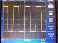
You speak with authority, but in the end you don't seem to have much background. Taking a look at the waveforms of a working unregulated push-pull with varying load (such as an audio amplifier) is so self explaining...
It's useful to avoid discussions like this.a small test video signal duty cycle and scop hope these results will have information about the circuit you
test video:
YouTube - SMPS & NMOS II
test video:
YouTube - SMPS & NMOS II
Attachments
a small test video signal duty cycle and scop hope these results will have information about the circuit you
test video:
YouTube - SMPS & NMOS II
so slow......... zoom in and check for rise and fall times- Status
- This old topic is closed. If you want to reopen this topic, contact a moderator using the "Report Post" button.
- Home
- Amplifiers
- Power Supplies
- new smps 800watt