got an amp-6-kit from 41hz.com and have the following problem. the power supply circuit looks like the following:
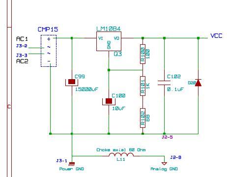
completed the circuit ecxept c99 and tested the output voltage. result: v(out)=9,7vdc. bad. according to the formula provided by the ai the output voltage should equal v(out)=1.25*(1+(R101+R102)/R100)) i.e with the given resistors it should be 14,6v.
i measured the following things:
v(in)ac at CMP15 = 16,0v
v(out)dc at CMP15 = 14,9v
v(out) at lm1084 measured at c99 and d20 = 9,7v
v(in)-v(out) at lm1084 = 5,55v
instead of the lm1084 as shown in the shematic 41hz.com provided an ld1585,if i understand the data sheets right they seem to be interchangeable.
mounted a 12v/20w bulb in series to see if the circuit draws significant current. bulb stays completely dark, not the slightest glow visible.
if i get it right, a mounted bulk cap c99 should raise v(in) at lm1084 from 14,9v to about 18v. am i right when i assume that this doesn't influence v(out) at lm1084, since v(out) is determined by the values of the resistors r100, r101 and r102? imo the additional 3,1v should only lead to more heat dissipation at lm1084, but not to a raise of v(out).
any helpful coments?
please note that this is my first diy-project, so my knowledge is rather basic. i know about the basic components, but not much about how they work together in the different circuits, i know basics about measuring. my soldering is good, so this shouldn't be the reason for the fault.
Uh-uh: "...completed the circuit ecxept c99 ..." - This is definately a NOGO for that regulator. If you provide AC input the bulk capacitor C99, following the bridge-rectifier, is compulsory for a correct function of the regulator. Without C99 the regulator 'sees' a pulsating DC voltage which makes no sense if you want to have a nice looking DC voltage at the output.
With C99 attached you should read a DC voltage of about 16,0V * SQRT(2) - 2 * Vdiode across C99 - which results in approx. 16Vac * 1,414 - 2 * 0,7V = 21,2Vdc.
With C99 attached you should read a DC voltage of about 16,0V * SQRT(2) - 2 * Vdiode across C99 - which results in approx. 16Vac * 1,414 - 2 * 0,7V = 21,2Vdc.
- Status
- This old topic is closed. If you want to reopen this topic, contact a moderator using the "Report Post" button.