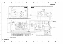
That's a very bare bones circuit  I see no snubbers on the primary or secondary of the power transformer. Where ever you got the circuit from i hope it told you what type of transformer to use & turns ratios, ferrite material etc. Also no mention of input filtering apart from a simple block diagram, you'll need a couple of filter types to prevent noise getting back into the mains
It's also non regulated, i do hope you realise that.
I see no snubbers on the primary or secondary of the power transformer. Where ever you got the circuit from i hope it told you what type of transformer to use & turns ratios, ferrite material etc. Also no mention of input filtering apart from a simple block diagram, you'll need a couple of filter types to prevent noise getting back into the mains It's also non regulated, i do hope you realise that.
Actually, you can build very nice and small SMPS using IR2153 ( without output voltage regulation ). But your schematic need little improvements ( you need to add snnubers, inpu NTC, and some kind of overcurrent limit.
You can find lots of stuff on net.
I am very happy with my IR2153 based smps.
You can find lots of stuff on net.
I am very happy with my IR2153 based smps.
Attachments
Actually, you can build very nice and small SMPS using IR2153 ( without output voltage regulation ). But your schematic need little improvements ( you need to add snnubers, inpu NTC, and some kind of overcurrent limit.
You can find lots of stuff on net.
I am very happy with my IR2153 based smps.
You tried the SMPS in the above schematic?
I think the only problem there is the IGBTs, i am trying to replave them with any other model.
hello i found this IR2153 based smps and i don't know if it's ok ive bought all the parts but im scared to go ahead whit the build..."im new in smps build"...thanks
Some BLOWUPS, may occure with this design. be carfull
You tried the SMPS in the above schematic?
I think the only problem there is the IGBTs, i am trying to replave them with any other model.
No that exactly. I'm using mosfets, not igbt. It 's similiar to this classd.ru, with overcurrent protection.
I want to do the source that the scheme does not look so complicated and I think I can handle. I originally wanted to buy ready-made boards from those who sell on the forum but not serious and treat me with indifference and reacted angrily when I made public that in fact what they sell is not functional yet. so I decided to do one source alone to show that it can be. I have to publish every stage of progress source here.
The circuit needs some modifications, but i've builted my first prototpye SMPS something like that (SPafi's very simple schematic). So it is really good for a start.
Instead of IRFP460 use IRF740 or IRF730, (much lower gate charge and cheaper). The 64k supply resistor should be lowered to 33k or 22k if more current need to drive FETs, but you should use an 5W resistor (the IC contains an internal 15V zener to supply itself).
You should not need 1000uf 200V caps, bit lower should be enough too. You can get about 100W easily, with a small ETD29 transformer, that should be enough for testing, driving small amps.
The circuit needs some modifications, but i've builted my first prototpye SMPS something like that (SPafi's very simple schematic). So it is really good for a start.
Instead of IRFP460 use IRF740 or IRF730, (much lower gate charge and cheaper). The 64k supply resistor should be lowered to 33k or 22k if more current need to drive FETs, but you should use an 5W resistor (the IC contains an internal 15V zener to supply itself).
You should not need 1000uf 200V caps, bit lower should be enough too. You can get about 100W easily, with a small ETD29 transformer, that should be enough for testing, driving small amps.
Hi,
If You want can put complete simple scheme with this IC IR21531. i develop for any companies 2001 (now is free)
I have resolved three points on this circuit.
at switch-off stopped immediatelly.( normally ,decrease with continuos re-start)
protection short-cut (also at start see if ok) this is a problem with this ic, because pseudo-soft-start not have sense (start with fixed pwm and delay to start not save...explosion of mosfet)
use simple EE32 for 250w out (audio peak) not continuos resistive load.
use mosfet 38nb40 to-247.
regards
Last edited:
Hi,
If You want can put complete simple scheme with this IC IR21531. i develop for any companies 2001 (now is free)
I have resolved three points on this circuit.
at switch-off stopped immediatelly.( normally ,decrease with continuos re-start)
protection short-cut (also at start see if ok) this is a problem with this ic, because pseudo-soft-start not have sense (start with fixed pwm and delay to start not save...explosion of mosfet)
use simple EE32 for 250w out (audio peak) not continuos resistive load.
use mosfet 38nb40 to-247.
regards
Hello AP2 ...
I would like to test the schematic, i have a chip on hand (Ionutzxop old board) and i want to make the smps for him. I wanted to use that yamaha schematic + modifications and Mosfet not IGBT + ETD44 core.
but if yours is simpeler I could try it
Best regards,
Savu Silviu
I think circuit simple yet,but lots of parameter can make it unstability,I know QSC ,YAMAHA and other pro amplifier use such circuit topology,but anyone can send us one formula that can calculate L and C with series-resonance circuit(ZVS mode).otherwise anyone can not make it work stable and cool.
Hello AP2 ...
I would like to test the schematic, i have a chip on hand (Ionutzxop old board) and i want to make the smps for him. I wanted to use that yamaha schematic + modifications and Mosfet not IGBT + ETD44 core.
but if yours is simpeler I could try it
Best regards,
Savu Silviu
Hi Savu,
ok,I put tomorrow because I have to remove some parts from the scheme (includes other functions).
Yes You can use IR2153 (difference is only diode bootstrap incluse on IR21531D)
I think with ETD44 this circuit is good up to 600W (not regulated ).
Regards
I think circuit simple yet,but lots of parameter can make it unstability,I know QSC ,YAMAHA and other pro amplifier use such circuit topology,but anyone can send us one formula that can calculate L and C with series-resonance circuit(ZVS mode).otherwise anyone can not make it work stable and cool.
Yes, I full agree.
I can put only schematic for this chip.
formula change with any type of inductor and it is not pure theoretical application
Regards
Hi,
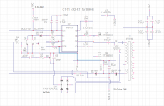
This is IR21531 scheme (not regulated PSU)
it is simple and good collaudate, sure... not suitable for audiophile amplifiers but eg. for sub is very good up to 600w.
( power is in relation of some components value)
D4-D3 is a simple "PUMP-CIRCUIT" for replace 50hz trafo 12V.
at switch-on,C4-Q4 create a small imbalance pwm(for very small time) (this reduce charge-current on primary)
Regards
Attachments
Hi AP2.
Today i recieved 25 pcs of ir2153.
I will try you're proposal.
I will keep you updated when i start to work on it (bussy at work for the moment).
Many thanks,
Savu Silviu
Hi savu,
yes np, tell me when is ready,also when traspose this circuit from CAD, put a small mistake on q4. after I put output circuit with lc filter e datasheet for realizze good trafo.
this power supply remaining quiet for 600w sub amplifier.
regards
Actually, you can build very nice and small SMPS using IR2153 ( without output voltage regulation ). But your schematic need little improvements ( you need to add snnubers, inpu NTC, and some kind of overcurrent limit.
You can find lots of stuff on net.
I am very happy with my IR2153 based smps.
what is the true valor of pr101?? is a ptc resistor or ntc resistor?
Hi,
This is IR21531 scheme (not regulated PSU)
it is simple and good collaudate, sure... not suitable for audiophile amplifiers but eg. for sub is very good up to 600w.
( power is in relation of some components value)
D4-D3 is a simple "PUMP-CIRCUIT" for replace 50hz trafo 12V.
at switch-on,C4-Q4 create a small imbalance pwm(for very small time) (this reduce charge-current on primary)
Regards
ur above scheme in working condition = ?
if s then give hear trans. ditails.
SOORY FOR MY BAD ENG. LANG.
ur above scheme in working condition = ?
if s then give hear trans. ditails.
SOORY FOR MY BAD ENG. LANG.
Hi,
Yes, it work. I test up to EE42 trafo for 1,2kw. (two amp at bridge for sub).
no problem. Is clare, not adeguate without experience in high-voltage/ pcb development and trafo.
Regards
- Status
- Not open for further replies.
- Home
- Amplifiers
- Power Supplies
- simple SMPS