Hi all,
I have an active eq project in the works and I'm building a multi channel amp to power the speakers. I got this bombing reclaimed toroid transformer from Steve at ApexJr. but have been unable to locate a diagram for the primary and secondary leads on it. If there were just a few I would use careful trial and error to figure it out but this has more than 20 leads with some colors repeating.
Two weeks of inquiry at Amveco has established that this is a proprietary and archived product for which they are unwilling and unable to share any information.
So here's what I have:
Amveco transformer # AA 21528E
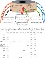
0-100-110-120V primaries
secondaries: 120V @ 3.5A, 21V @ 19A (this is the one I need,) 8.5V @ 10.5A, 37V @ 3A, 12V @ 0.2A
There are a pair each of 10 and 14 gauge leads, 12 - 16 gauge and 6 - 18 gauge.
I don't have access to a variable power supply.
What is the safest and smartest way to determine what is what?
I have an active eq project in the works and I'm building a multi channel amp to power the speakers. I got this bombing reclaimed toroid transformer from Steve at ApexJr. but have been unable to locate a diagram for the primary and secondary leads on it. If there were just a few I would use careful trial and error to figure it out but this has more than 20 leads with some colors repeating.
Two weeks of inquiry at Amveco has established that this is a proprietary and archived product for which they are unwilling and unable to share any information.
So here's what I have:
Amveco transformer # AA 21528E
0-100-110-120V primaries
secondaries: 120V @ 3.5A, 21V @ 19A (this is the one I need,) 8.5V @ 10.5A, 37V @ 3A, 12V @ 0.2A
There are a pair each of 10 and 14 gauge leads, 12 - 16 gauge and 6 - 18 gauge.
I don't have access to a variable power supply.
What is the safest and smartest way to determine what is what?
Last edited:
Hi,
do you have another transformer with a small output voltage? I would use a multimeter first, to test connections (and resistance to appraise primary and secondary sides) and after that a small AC-Voltage to see the proportion of the connections. Normally, the sequence of the wires is equal to the taps of the coil.
I don't know another way without a datasheet/ wiring-diagram, so I hope this helps you. The thickness of the wires may also help you sorting them.
Thanks for the reply,
I have tested for continuity and isolated all winding pairs. There is no center tap, so that potential complication is out.
The problem is that the resistances between these pairs are so similar, all under 1 Ohm and most around 0.3. (My meter only reads to tenths of an Ohm.)
Can I at least assume that the two heaviest gauge wires are primary leads? Then I could hook up a 12V transformer as you suggest to deduce the others.
I thought that multiple primaries would all be tapped off the same winding and I could sort them in order of resistance, but none of the pairs I have isolated have continuity with any other.
thanks,
gary
a 12V AC feed as suggested is all you need.
I would guess the 19A secondary is the heaviest gauge.
The 1-100-110-120 tapped primary will have a common terminal and slightly increasing resistance. Connect the 12VAC across the outside (highest pair)
Alternatively, if you put 12VAC across the heaviest pair (21V-19A) then you'll get about 70VAC off the primary (careful!) and can identify taps with a voltmeter( more accurate)
I'd screw all the leads into a terminal block or onto a wood board to prevent the possibility of shorts and to make it easier to know where lethal voltages are.
Don't kill yourself")
I would guess the 19A secondary is the heaviest gauge.
The 1-100-110-120 tapped primary will have a common terminal and slightly increasing resistance. Connect the 12VAC across the outside (highest pair)
Alternatively, if you put 12VAC across the heaviest pair (21V-19A) then you'll get about 70VAC off the primary (careful!) and can identify taps with a voltmeter( more accurate)
I'd screw all the leads into a terminal block or onto a wood board to prevent the possibility of shorts and to make it easier to know where lethal voltages are.
Don't kill yourself
The windings are specified as volts per turn. So the primary has the highest number of turns ( 120V ) . I notice you have a 120 V secondary winding also.
You have a primary with the highest wattage rating ( wattage of all secondaries windings) and another 120V ( secondary with lower wattage rating).
So the primary 120V winding should have a heavier guage...lower resistance....than the secondary 120V winding. Confirm the other windings all have lower resistance and then apply a mains voltage to the primary or secondary winding via a 120V filament bulb. Determine the voltages on all windings and scale them up to reflect 120 V on the primary. Secondary wire will be thinner than the primary on the 120 V tap.
You could use a step down transformer to get a low voltage for testing like 12 V or so. Might still be a good idea to use something to protect from internal shorts like a fuse or a filament lamp on the primary side.
Thanks Ashok,
your figures raise a few questions especially in light of my voltage readings. Attached is a diagram of the toroid being supplied by a smaller (50VA) 12V transformer. The resistance readings and gauges are listed under the transformer, and there is a chart reflecting leads attached to this 12V supply on top. I am thinking that I shouldn't be getting any voltage over about 13V so the leads I supplied that gave me readings over 15V (150 with 120V mains) on any other pair I assumed were secondaries.
I have labeled my guesses with question marks next to them but I don't know what all the other leads are.
Am I on the right track here?
thanks,
gary
Attachments
Hi Gary,
I think you cracked the problem.
I've listed out the calculations. I selected one pair of cables you applied 12 V to and normalised all the other readings taking the first one as 1. I just assumed it looked like a Primary coil.
After that I multiplied all others with 100 volts on that pair. The result as you can see is perfect !
You have two primaries which take 100 volts ( P1 and P2 ). Then for 110 volts you add a coil in series which has 10 volts to give 110 volts. Add another 10 volts to that to get 120 volts. You have two sets. So P1 is 100 V , P1a is 10 V and P1b is another 10 V. Same way with P2 .
You will need to ensure that polarities are proper otherwise the added series coil will subtract rather than add. You can easily sort this out ( right now) by connecting them is series and see if the measured voltage goes up and mark out what colours are to be connected. Simple ( 100 + 10 + 10 ).The secondaries are self explanatory !
Cheers.
Attachments
Looks like the attached file doesn't work.
Here is another one.
Edit:
I'm having a problem. I can open this attachment from the original file on my hard disk. However after uploading it I can't open the file. After downloading it Word tells me that I need to install some feature to enable it to open the file ! Any reason for this ?
Here is another one.
Edit:
I'm having a problem. I can open this attachment from the original file on my hard disk. However after uploading it I can't open the file. After downloading it Word tells me that I need to install some feature to enable it to open the file ! Any reason for this ?
Attachments
Last edited:
It's time for me to turn in for the night. Since I'm not sure if you will have a problem with the .doc file from the earlier post, I'm attaching a copy as a text file using Notepad. Look at it full screen otherwise the lines could get mixed up.
Cheers.
Cheers.
Attachments
I tried to open the doc file again using my second computer but it still says the file is corrupt. Wonder if it has anything to do with my ISP ? Many PDF files from this forum will not open either !
Yes Andrew , it's safer to test terminals when they are safely connected to a screw terminal. But often the urge to get it done quickly is so strong that.....
.............we do it the dirty way ! Invites blue smoke of course .....at times!
Now I am going to bed. Have a great day to all those who's day has just started and good night to the rest of you .
Yes Andrew , it's safer to test terminals when they are safely connected to a screw terminal. But often the urge to get it done quickly is so strong that.....
.....
........we do it the dirty way ! Invites blue smoke of course .....at times! Now I am going to bed. Have a great day to all those who's day has just started and good night to the rest of you .
- Status
- This old topic is closed. If you want to reopen this topic, contact a moderator using the "Report Post" button.
- Home
- Amplifiers
- Power Supplies
- safest way to identify primary/secondary?