I suppose I am getting a little more serious about electronics now and I feel I need some good test equipment. I just went out and bought an Instek DDS function generator and now I want a nice benchtop switching power supply. I have seen these online for sale, but they seem to run atleast $300 for what I want, and these supplies don't have digital control (you can not "type in" what voltage/current you want).
I figure it might be worth my while to try to design a good smps to meet my needs. Something in the range of 0-50v and 0-5a seems about right. While I have seen many linear power supplies online, few have digital control and even fewer use PWM. Maybe the reason that the kind of supply I want is so expensive is because it is very hard to design one?
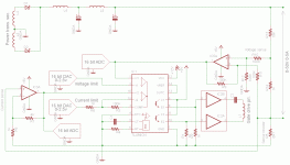
Anyway, I wanted to have a stab at it, so here is my design using at TL494, some ADC's and some DAC's. The DAC's set the comparison voltage that the 494 sees for current and voltage feedback. The ADC's are optional but allow for the microcontroller to know in real time what the current and voltage output of the power supply is. I intend to use an AVR micro to control the DAC's so that the user's voltage and current requirements can be met. I would also like to use a cheap LCD module to display the voltage output, current output, and current limit in real time.
My design uses dfferential voltage sensing so that the voltage drop across the current sense resistor does not cause voltage errors that grow with current output.
I have several questions for those more experienced than me:
1. Am I likely to have problems trying to achieve very low output voltages due to the fact that I am trying to use single supply opamps and their outputs will never really get to 0v? How close can a good rail to rail opamp get? Within say 10mv or so?
2. How good is a TL494 at dealing with very small input voltages? If i want my powersupply to output 1v for example, I will be feeding 50mv into the inputs of the opamp inside the 494. I believe I am concerned with the common mode input range here and the error at very small input voltages?
3. Is this design workable or possibly fundamentally flawed?
Maybe an expert knows how a real digitally controlled smps works and can shed some light on their design for me!
I figure it might be worth my while to try to design a good smps to meet my needs. Something in the range of 0-50v and 0-5a seems about right. While I have seen many linear power supplies online, few have digital control and even fewer use PWM. Maybe the reason that the kind of supply I want is so expensive is because it is very hard to design one?
Anyway, I wanted to have a stab at it, so here is my design using at TL494, some ADC's and some DAC's. The DAC's set the comparison voltage that the 494 sees for current and voltage feedback. The ADC's are optional but allow for the microcontroller to know in real time what the current and voltage output of the power supply is. I intend to use an AVR micro to control the DAC's so that the user's voltage and current requirements can be met. I would also like to use a cheap LCD module to display the voltage output, current output, and current limit in real time.
My design uses dfferential voltage sensing so that the voltage drop across the current sense resistor does not cause voltage errors that grow with current output.
I have several questions for those more experienced than me:
1. Am I likely to have problems trying to achieve very low output voltages due to the fact that I am trying to use single supply opamps and their outputs will never really get to 0v? How close can a good rail to rail opamp get? Within say 10mv or so?
2. How good is a TL494 at dealing with very small input voltages? If i want my powersupply to output 1v for example, I will be feeding 50mv into the inputs of the opamp inside the 494. I believe I am concerned with the common mode input range here and the error at very small input voltages?
3. Is this design workable or possibly fundamentally flawed?
Maybe an expert knows how a real digitally controlled smps works and can shed some light on their design for me!
Attachments
I didn't really look at your schematic, and am not too familiar with the TL494 anyway. SO someone else would have to answer question #3. But for question #2, it seems like feedback should tend to take care of any problem, there. For question #1, you'll need to look at some opamp data sheets. It should all be in there.
By the way, there is a neat-looking bench power supply schematic on page 146 of application note AN-84f from linear.com. It does 0v to 100v at currents ranging from 8A to 2A, and has independent linear constant-current and constant-voltage controls. It might be interesting, for another project, to make it digitally controllable, with digital readouts.
For yet-another project, I think that it would be handy to have a dual-polarity supply, with 0 to +50v and - 50v, or maybe even 0 to +100v and - 100v or more.
Have fun!
- Tom
For a bench power supply I would consider a linear output regulator. It's difficult to get fast current limiting and at the same time attenuate output ripple enough to prevent it from appearing on the oscilloscope when you are powering and measuring another circuit.
But dissipation may be greatly reduced by feeding this linear regulator from a tracking pre-regulator, that would be a SMPS whose regulation loop keeps a fixed voltage drop across the linear regulator.
Another option would be a clocked class D output stage with several notches to tame carrier residual and its harmonics, and fed from a SMPS, but I think the first idea combines the best of both worlds.
Concerning your circuit, have you thought about stability and frequency compensation?
Last edited:
Your going to alot of trouble there for a bench supply when they are readily available on ebay as used equipment for low prices. The digital thing isnt really required for amateur use , it's really intended for repeatability and audited testing in production environments.
Also difficult to remove residual noise on SMPS. Linear with pre-regulator is best. Meters on supplies should be used for indication only , an accurate test meter should always be used for setting output.
You will be able to get a supply with current limit , output down to zero volts , crowbar over volts protection , programmable functions ,output current sensing compensation etc , off ebay , look for stuff from Kepco , Kikusui , Kenwood , Lambda.
Just my 2 cents, current limiting in this matter would not be preferable as it would respond quite slow (IE output capacitor charge). Also you would like a bench supply just to make this ") running it from the mains directly for testing would be to dangerous. You could make a linear design and use a SMPS for powering your circuit, you could give feedback to the smps to regulate synchronous with the linear circuit to prevent extreme heat and losses. This way it would be fast and can be made pretty small because of the low losses.
running it from the mains directly for testing would be to dangerous. You could make a linear design and use a SMPS for powering your circuit, you could give feedback to the smps to regulate synchronous with the linear circuit to prevent extreme heat and losses. This way it would be fast and can be made pretty small because of the low losses.
running it from the mains directly for testing would be to dangerous. You could make a linear design and use a SMPS for powering your circuit, you could give feedback to the smps to regulate synchronous with the linear circuit to prevent extreme heat and losses. This way it would be fast and can be made pretty small because of the low losses. - Status
- This old topic is closed. If you want to reopen this topic, contact a moderator using the "Report Post" button.