Could I use the IRF820 instead? With the same values?
I'm thinking of building a Gyrator for my Baby Huey EL84. Maybe even two. And I have IRF820's in my parts bin.
I know very little about solid state things like mosfets, hence my question.
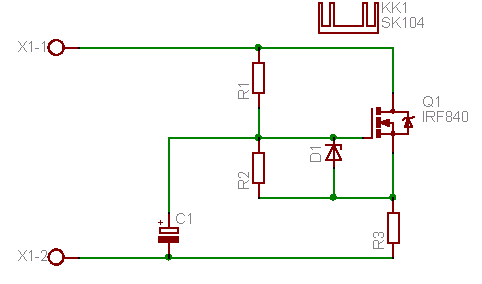
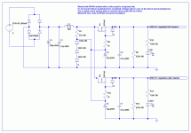
R1, R2 330k Ohm
C1 4.7uF
D1 ZD15
R3 33 Ohm
Q1 IRF840
Also any tips for improving this gyrator?
I'm thinking of building a Gyrator for my Baby Huey EL84. Maybe even two. And I have IRF820's in my parts bin.
I know very little about solid state things like mosfets, hence my question.
R1, R2 330k Ohm
C1 4.7uF
D1 ZD15
R3 33 Ohm
Q1 IRF840
Also any tips for improving this gyrator?
Attachments
Last edited:
The 820 will do less current than the 840. Look on the datasheet to see if it sufficient for your needs.
Thanks Richard,
I'm looking at 80mA per gyrator. The 820 can handle 2,5A the 840 something like 8A. That is the spec Id.
But I'm not sure how to transfer that current rating into the rating of the mosfet as it has been used in the circuit.
I'll just build it and see...
I'm looking at 80mA per gyrator. The 820 can handle 2,5A the 840 something like 8A. That is the spec Id.
But I'm not sure how to transfer that current rating into the rating of the mosfet as it has been used in the circuit.
I'll just build it and see...
Last edited:
I think at that current it should be fine. What voltage will be across it? You also need to consider the power dissipation and that you are within the device safe operating area (SOA curve) again both are on the datasheet - former in the table, latter as a graph.
Around 360 I reckon. Don't know for sure yet. Still have to build the amp. Going to use tube recifier. And the transformer is 360 VAC.What voltage will be across it?
Also any tips for improving this gyrator?
Yeah.
Send R1 to a regulated voltage. You'll give it great PSRR 🙂
Cheers!
Do you mean regulate the voltage before it gets to this gyrator? Or how should I see this?Send R1 to a regulated voltage
Cheers,
Bas
Like the second image here:
http://www.diyaudio.com/forums/blogs/geek/104-underappreciated-hybrid-mu-follower.html
Only you want to take your output from the anode (gyrator) rather than that images source (follower).
Cheers!
http://www.diyaudio.com/forums/blogs/geek/104-underappreciated-hybrid-mu-follower.html
Only you want to take your output from the anode (gyrator) rather than that images source (follower).
Cheers!
Bas,
This is not a strict gyrator. Despite that, it has two advantages. You can adjust output voltage(vary R3) and it has a lot less ripple than a typical MOSFET gyrator. Still it has the exactly the same high Zout. C3 is not part of the gyrator.You might also change R1, C1 to your values if this suits you better.
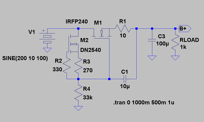
This is not a strict gyrator. Despite that, it has two advantages. You can adjust output voltage(vary R3) and it has a lot less ripple than a typical MOSFET gyrator. Still it has the exactly the same high Zout. C3 is not part of the gyrator.You might also change R1, C1 to your values if this suits you better.
Last edited:

But I'll think I'll go for your schematic Lars. Could I use the IXTH 20N50D? Instead of the IRFP240 Because I'm going to have those in my parts bin soon. Any changes? Sorry about all the questions. But I'm clueless on anything solid state.
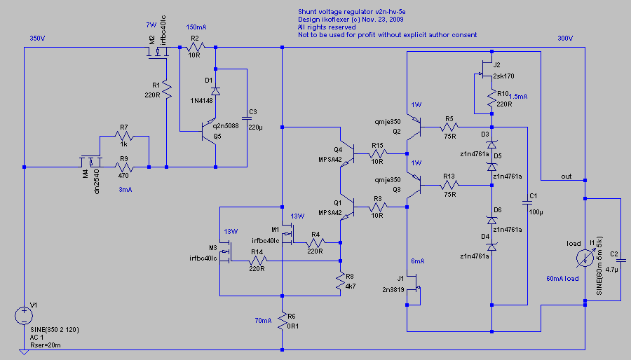
Of course, when in the mood and want to shoot for the stars you could go for the full shebang low output impedance shunt reg with everything on it 😀
The zeners can be replaced by suitable resistors to get lower noise.
The zeners can be replaced by suitable resistors to get lower noise.
Phew...how about a pcb...Groupbuy anyone 😉when in the mood and want to shoot for the stars
But I'll think I'll go for your schematic Lars. Could I use the IXTH 20N50D? Instead of the IRFP240 Because I'm going to have those in my parts bin soon. Any changes? Sorry about all the questions. But I'm clueless on anything solid state.
That would work. But the CCS depletion FET should be small like a DN2540 or LND150 as you should only run 1-5mA through it.
Don´t watse to much energy on this as you don´t know if it will pay off sonically in the end. Invest in some good motor-run caps they are usable whatever solution you decide. The OS RIFAs I use, are polypropylene in oil. You might end up with an old CLCLC.... PSU.
My idea was to use a small 2uF (Obbligato pp in oil)->10H->30uF PP (shared) and then branch to WW resistor 10 ohm->30uF Obbligato PP in oil per channel. Then I saw the gyrator thing and Menno van der Veen's white paper on his "electronic choke" and I thought I'd like to try that in the future.Don´t watse to much energy on this as you don´t know if it will pay off sonically in the end. Invest in some good motor-run caps they are usable whatever solution you decide. The OS RIFAs I use, are polypropylene in oil. You might end up with an old CLCLC.... PSU.
Things can get so out of hand quickly 😉
Last edited:
Another circuit to consider would be salas' simplistic high voltage regulator. Quite a few people have built that one and are happy with it.
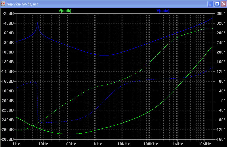
I like Lars' circuit. For something quick that's the one I'd also go for, it has good psrr. I'm not very familiar with the baby huey amp and how much it would benefit from a low output impedance supply. But if it would, then check this out. A bit of simulation here. The green line is a shunt regulator, the blue line is Lars' circuit. It is unfair to compare the two, one being easy to implement and requiring only a few parts to build, while the other being a project in itself. I'm working on a pcb for the regulator but I don't have that much time for the hobby lately, so progress is slow.
PSRR
ZOUT
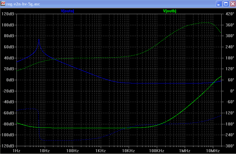
Thanks Iko.
What PSSR figure would be given to a gyrator, Lars's circuit and yours? If one had to put it on a sales brochure or datasheet. (I guess what I'm asking is for what frequency does one give those figures? Is it an average or is for the 100/120Hz freq.
Menno van der Veen and Tentlabs claim >40dB for a classAB amp and >60dB* for a classA amp for their 70 Euro Electronic Choke.
* Apparently the circuit can be optimized if you know the current draw is constant.
Last edited:
- Home
- Amplifiers
- Power Supplies
- Mosfet Gyrator using the IRF840