Hi everybody, first post here!
I'm currently designing a quad linked VCA compressor for my final year project at university, and I've hit a bit of trouble with the AC rectification for the control voltage.
The control voltage signal so far consists of a full wave precision amplifier and a low pass sallen-key filter with Fc of 20Hz & gain of 1.6. The aim of this is obviously to remove the audio component of the input signal. This setup gives a perfectly smooth RMS DC voltage at 1kHz, however as the frequency of the input increases a problem occurs with the rectifier and I have no clue what is causing it.
As the frequency increases the rectifier stops working and I am seeing very large negative pulses resulting in DC offset after my filter. However, this problem only started happening after adding the S-K filter on the end of the rectifier.
I have no idea how I am getting these large negative spikes from the rectifier (-6V for a 2Vp-p input!) so any help whatsoever would be great. My knowledge of the whole system is quite limited so its likely that I'm missing something very obvious!
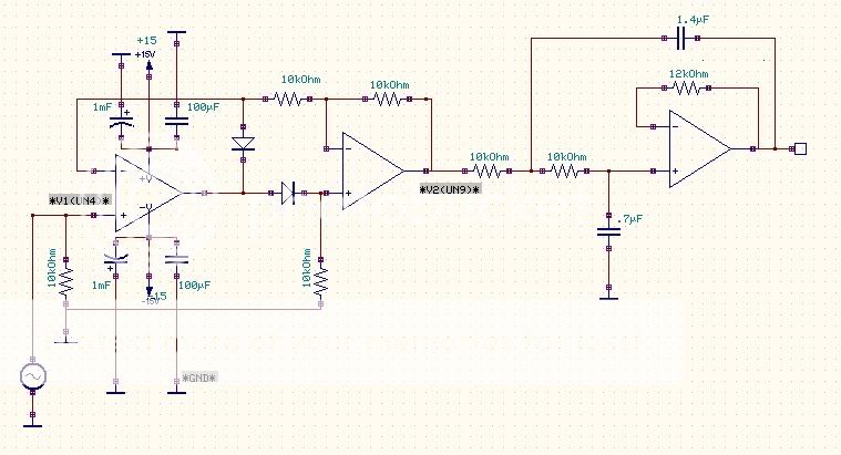
Ok, I've got some screenshots to help explain the problem a little better. Here is the schematic of the circuit, with reference points V1 (input) and V2 (output) for the following simulations:
http://i6.photobucket.com/albums/y242/dan_thompson87/schematic.jpg
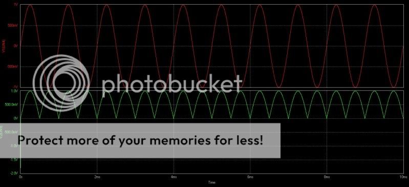
Simulation for 1Vp-p at 1kHz:
http://i6.photobucket.com/albums/y242/dan_thompson87/rectifier.jpg
Simulation for 1Vp-p at 15kHz:
http://i6.photobucket.com/albums/y242/dan_thompson87/15krectified.jpg
The only thing changing between the 2 simulations is the frequency of the input voltage!
Thanks")
http://i6.photobucket.com/albums/y242/dan_thompson87/schematic.jpg
Simulation for 1Vp-p at 1kHz:
http://i6.photobucket.com/albums/y242/dan_thompson87/rectifier.jpg
Simulation for 1Vp-p at 15kHz:
http://i6.photobucket.com/albums/y242/dan_thompson87/15krectified.jpg
The only thing changing between the 2 simulations is the frequency of the input voltage!
Thanks
I've just tried with the LP filter disconnected and I'm still getting the problem - so it must have been there all along. I've got some screenshots of the schematic and the simulations below.
Schematic (reference points V1 and V2 correspond to the simulations)
Simulation for 1Vp-p at 1kHz:
Simulation for 1Vp-p at 15kHz:
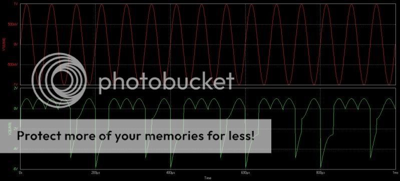
The only thing that is different between these 2 simulations is the frequency of the input. It's also worth mentioning that the negative spikes get greater in amplitude with frequency, e.g. 20kHz will have an even greater negative spike.
Thanks!
Schematic (reference points V1 and V2 correspond to the simulations)
Simulation for 1Vp-p at 1kHz:
Simulation for 1Vp-p at 15kHz:
The only thing that is different between these 2 simulations is the frequency of the input. It's also worth mentioning that the negative spikes get greater in amplitude with frequency, e.g. 20kHz will have an even greater negative spike.
Thanks!
Sorry about the double post, I didn't realise replies were moderated!
I've had a go deleting all of the nodes in the schematic layout and rewiring it all, and the problem is solved! It seems as though I deleted a component or connection somewhere but left the net intact.
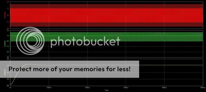
However, now I have the DC voltage a new problem has popped up! The capacitor is charging to the RMS value of the input as I would like it too, but it then drops by a few mV before levelling off. Is this just the nature of the circuit or is there a way I can keep it at constant RMS value? Here's a simulation to show what's happening:
1.747Vp-p/1.2VRMS (+4dBu line level) @ 1kHz
I have a feeling this may be something to do with the 12k feedback resistor in the filter. I was told earlier by my lecturer that a gain of 1.6 from the LP filter will improve the accuracy of the cutoff and give a flatter DC voltage. I have a feeling that this resistor is configured wrongly though as changing the value does nothing to my output voltage!
Also, is the initial charge time for the capacitor too long? 50ms is obviously a significant amount of time in a compressor circuit.
It's a TL074 op-amp chip by the way.
I've had a go deleting all of the nodes in the schematic layout and rewiring it all, and the problem is solved! It seems as though I deleted a component or connection somewhere but left the net intact.
However, now I have the DC voltage a new problem has popped up! The capacitor is charging to the RMS value of the input as I would like it too, but it then drops by a few mV before levelling off. Is this just the nature of the circuit or is there a way I can keep it at constant RMS value? Here's a simulation to show what's happening:
1.747Vp-p/1.2VRMS (+4dBu line level) @ 1kHz
I have a feeling this may be something to do with the 12k feedback resistor in the filter. I was told earlier by my lecturer that a gain of 1.6 from the LP filter will improve the accuracy of the cutoff and give a flatter DC voltage. I have a feeling that this resistor is configured wrongly though as changing the value does nothing to my output voltage!
Also, is the initial charge time for the capacitor too long? 50ms is obviously a significant amount of time in a compressor circuit.
It's a TL074 op-amp chip by the way.
Last edited:
A/ In the case of a TL074, the 12K is useless
B/ The overshoot is caused by a too high Q; try C values closer to their geometric average (~1µF)
C/ This rectifier reacts to the mean value of the waveform, not the rms
D/ Reducing the rise time can be achieved by increasing the order of the filter (for a given amount of ripple).
B/ The overshoot is caused by a too high Q; try C values closer to their geometric average (~1µF)
C/ This rectifier reacts to the mean value of the waveform, not the rms
D/ Reducing the rise time can be achieved by increasing the order of the filter (for a given amount of ripple).
Thanks for the responses, they're a big help.
Everything Elvee said made sense to me - I'm going to have a go at tweaking the cap values to give a better Q, as well as trying the next order filter.
Can someone please explain to me why the feedback resistor makes no difference on the TL074 please? Would it be better to pick a different chip where it will make a difference, or exclude it altogether?
Sorry if my questions seem trivial - I only have basic knowledge of how these circuits work and I'm in the process or learning at the moment. That's the idea of a dissertation right?
Can someone please explain to me why the feedback resistor makes no difference on the TL074 please? Would it be better to pick a different chip where it will make a difference, or exclude it altogether?
12k acts the same as a wire link. The input impedance of the amp is so high, and the input bias current so low that an extra 12k is irrelevant, might as well tie input directly to output.
Any resistor there will behave much like a wire link, unless you start using a value that starts approaching the amp input impedance - but that will cause other problems, like noise pickup, & offset voltage effects.
With 12k there, IF you put another resistor from the (-) input to ground, then you'd have voltage divider action going on in the feedback path, which would alter the filter gain.
What are the desired specs? i.e. How low does the input frequency need to be able to go? And how flat does the DC output need to be? You might have trouble at low frequencies. I once designed one of these that had to be fast and work from 30 Hz to 22 kHz, and had to resort to some trickery to adjust some of the circuit parameters versus frequency.
By the way, have you tried LT-Spice? You can use WAV files as inputs (and outputs), with LT-Spice. It's free, at linear.com . And there's a truly-excellent support group for it, at yahoogroups.com.
By the way, have you tried LT-Spice? You can use WAV files as inputs (and outputs), with LT-Spice. It's free, at linear.com . And there's a truly-excellent support group for it, at yahoogroups.com.
- Status
- This old topic is closed. If you want to reopen this topic, contact a moderator using the "Report Post" button.
- Home
- Amplifiers
- Power Supplies
- [help] Full Wave rectification for VCA control voltage