Situation: remodeling an older QSC-1400 amplifier. The transformer, chassis, switches, connectors and circuit breaker are "ruggedized" and worth using, but there is no secondary center tap(s), just two secondaries of ~ 55 VAC, each (as wired for the two 120 VAC primaries).
I know it can be done ... maybe just use the powerline ground to chassis as the "center" and signal & DC power ground, but for audio equipment, I believe this would just leave to door open for more "hum" and other noise.
I guess I could reconnect the primaries (in series) for pseudo-240 VAC and then connect the secondaries in series for the desired ~55 / 0 / ~55. ...
What to do? Got recommendations? ...
Last edited:
It's common practice to use a full wave bridge and reference negative (or negative of one side and positive of the other on a +- supply to earth or common ground. This is indeed about as quiet as anything you can do. I would think it really depends on what you are building and it's power supply requirements.

Member
Joined 2009
Paid Member
yes, split rails ...
The transformer has two sets of windings, two primaries and two secondaries. When the primaries are parallel, they give ~55 VAC through each secondary, so putting the secondaries in series would give me twice the rail voltage needed for the amp. However putting the primaries in series and powering with 120 VAC and the secondaries in series I can get ~55 / 0 / ~55 and use the central connection as the center tap as is common practice ... as you obviously know ... but I can't use the amp in Europe where the wall power is about ~240 VAC.
I hate to waste a perfectly good chassis, transformer and all the parts (used ~US$50) ... so I'm planning on DC rail voltage of about + 76 / 0 / -76 VDC to power an older version of a set of amp modules like these: http://www.aussieamplifiers.com/nxv500.htm (prototype ~US$200 each)and using a power supply filter board like this: http://www.aussieamplifiers.com/psu.htm (used US$50) ... should = around 300 watts each into 8 ohms on modest heat sinks. (The old QSC has a very healthy transformer of > 900 VA, but the fan had to go, so by "derating" it a bit, hopefully ... it should live a long time. ... I believe a worth balanced input amp with decent power for a garageband PA = low cost as the total "all in" is less than US$600.
Last edited:
Member
Joined 2009
Paid Member
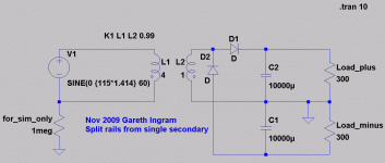
Well you can get split rails without a Centre tap although ripple is a little higher as a result you can probably deal with that if you want to.
Here's how it works (attached):
Wow, Man! Thanks a lot! I knew there was a relatively simple way to do it ...
As long as the guts of the thing are open to experiment, I'll give it a go.
BTW: this would be a half wave diode bridge, so I'll use fast, extra duty diodes and double up on capacitance.
Member
Joined 2009
Paid Member
Hum is your only risk as far as I can see. Most amplifiers have very good PSRR for their power hungry output stages. The issue is the front end of the amplifier. You should focus your effort on the front end, perhaps isolating the rails to the front end from the output stage by using a diode, resistor and capacitor to ground.
Member
Joined 2009
Paid Member
I must have some reality in that cigar, want a huff?
Don't take my word for it, ask around, try it yourself.
The QSC 1400 is a fairly high power amplifier and requires some hefty current. A doubler will not provide it as it will (in a perfect world) half the available current while it doubles the voltage.
Ah and then there's the ripple...
Don't take my word for it, ask around, try it yourself.
The QSC 1400 is a fairly high power amplifier and requires some hefty current. A doubler will not provide it as it will (in a perfect world) half the available current while it doubles the voltage.
Ah and then there's the ripple...
surely the power is limited by the Trafo and not the topology of the rectifier.
But voltage doublers draw a lot of peak current, with a lot more space in between charging pulses comapred to a normal full wave. The higher peak currents cause more sag from the trafo, and the caps get drained more before getting replenished. All of this conspiracy works against you to produce less voltage under a given DC load.
Member
Joined 2009
Paid Member
I maintain that the power available is limited by the trafo. If you want split rails from a single winding, it's possible to do so with a simple circuit. With half-wave you only have two diodes, so peak current is higher and also the corresponding ripple voltage for a given capacitance. No free lunch.
In terms of whether this is the right thing to do for a particular amplifier - well that's a different question altogether.
[John - you gotta stop growing that reality tobacco in your basement]
In terms of whether this is the right thing to do for a particular amplifier - well that's a different question altogether.
[John - you gotta stop growing that reality tobacco in your basement
]I take it you didn't ask around and try it?
Although the measured output voltage of a voltage multiplier may be several times greater than the input voltage, once a load is connected the value of the output voltage decreases. Also any small fluctuation of load impedance causes a large fluctuation in the output voltage of the multiplier. For this reason, voltage multipliers are used only in special applications where the load is constant and has a high impedance or where input voltage stability is not critical.
Ive use the half wave voltage doubler for many curcuits and it works well with Low current opamp duty and can be fairly quiet but you need to use a lot more Capacitance , at least double , and they do tend to sag under a load ....
I tried to use one with a TDA2040 and a 16v 5a Transformer trying to get +/-22v DC and 4700uF per rail ... the result was a lot of hum and an extreme drop in the voltage down close to +/-14v dc ......
I tried to use one with a TDA2040 and a 16v 5a Transformer trying to get +/-22v DC and 4700uF per rail ... the result was a lot of hum and an extreme drop in the voltage down close to +/-14v dc ......
You don't connect the primaries in series, if you do that you will only get 27.5-0-27.5 at the secondary side.
If you look at the schematic on the first page of the PDF you linked to, it shows how they make a pseudo ground for each winding by a series connected pair of big caps. I would add balancing resistors as an extra precaution.
If you look at the schematic on the first page of the PDF you linked to, it shows how they make a pseudo ground for each winding by a series connected pair of big caps. I would add balancing resistors as an extra precaution.
Last edited:
Member
Joined 2009
Paid Member
I take it you didn't ask around and try it?
Why would I do that when I know everything there is to know
I may actually try it. This is why I was able to reply to the thread in the first place because I have been modeling such a supply. I have 4 nice transformers, each one has only a single secondary. I plan to build 4 amplifiers using them. Two of them will be single rail but I wanted the option to build another 2 using split rail. So I may actually try it out afterall !
- Status
- This old topic is closed. If you want to reopen this topic, contact a moderator using the "Report Post" button.
- Home
- Amplifiers
- Power Supplies
- No center tap Help