Discussion continuing from this thread http://www.diyaudio.com/forums/twis...p-bipolar-shunt-regulated-power-supply-7.html
Russ,
If you can accept some advice from someone who has been using this exact topology (CCS fed shunts) for over 30 years now - your advice on setting the running currents you gave a few posts ago is kinda fluffy.
1/ I feel you MUST add a current sense R in the emitter path of QN1, maybe 1 ohm or perhaps even less, but this is vital to ensure the shunt never runs out of current due to demands from the signal processing circuits it is powering. This R will not noticably worsen the OPZ of the regulator because there is so much loop feedback present, but it allows you to: a/ set an exact DC shunt current and b/ with a scope across this R, you can see if the signal circuits are draining the shunt on signal peaks and causing it to "dry up" momentary - and possibly even oscillate as it goes in and out of action.
2/ In my experience, a single bipolar does not make a good enough CCS to get the full sonic results from this topology. A compound of some sort will sound even better.
----------------------------------------
Early in the thread, someone was asking about the supposed benfits of this topology, and saying in their mind shunt & series were alike. No way!
One good benefit was given by someone else, saying it can absorb current from the signal circuits as well as supply current, but what hasn't been mentioned is the fact with a good CCS in the regulator, there is no signal based circulating currents in the power supply lines, and more importantly, the earth lines, upstream of the reg. All such currents are now pure DC.
This can make many circuits that were unstable (because of cross coupling in these lines) into very stable, which might save some headaches.
-----------------------------------------
Vacuum State has been selling a High voltage CCS'd shunt reg kit intended for tube equipment for over 15 years, and I'm happy to see the SS world is catching up. (grin)
Regards, Allen (Vacuum State)
Hi Allen,
1) Measuring/Scoping R5/R11 (Bipolar Schematic) can tell much the same information about the load without compromising output Z.")
2) In my experience the single bipolar CCS is more than adequate. Now could it be stiffer? Yes, but because of the extremely high OLG and feedback, it is not at all required that it be more stuff than it is. Still I am willing to consider a suggested topology.
I am sure CCS shunts are as old as dirt.
Cheers!
Russ
1) Measuring/Scoping R5/R11 (Bipolar Schematic) can tell much the same information about the load without compromising output Z.
2) In my experience the single bipolar CCS is more than adequate. Now could it be stiffer? Yes, but because of the extremely high OLG and feedback, it is not at all required that it be more stuff than it is.
Still I am willing to consider a suggested topology. I am sure CCS shunts are as old as dirt.
Cheers!
Russ
Hi Russ,
I have to agree with Allen regarding the quality of the current source. I have been using similar topologies since 1984, not as long as Allen, but developed independently, and long enough to understand the requirements. My circuit solutions have moved in different directions since then, but without fail, increasing the impedance of the current source improves the supply rejection from incoming interference.
The power supply rejection is governed by the ratio of the current source impedance to the shunt impedance.
The ideal current source has infinite impedance over the required operating frequency range. This is impossible within our current knowledge, but the closer we can approach this ideal the better the results will be.
Also the ideal power supply has zero impedance over the required operating range (not positive or negative impedance, but absolute zero impedance).
It is easy to generate an extremely low impedance using vast amounts of negative feedback but the penalty when using typical circuit solutions with enormous amounts of negative feedback usually requires gross overcompensation to keep things stable. This results in a regulator with a slow reaction time to load transients. Present the regulator with a fast load transient and the regulation falls apart. This is not good when the load transients are being clocked in tens of MHz or for that matter at audio frequencies.
Relying on high frequency decoupling capacitors is also subject to the capacitor quality, which can be quite variable in the frequency domain as no capacitor is perfect. Even the circuit layout has profound effects as you have found with the I/V output lines, power supply distribution and the general layout of the dac board.
There is more to designing a power supply and the overall circuit system than meets the eye!
Please do not take this as an attack on your credentials as I believe you and Brian have produced a great product series, with the Buffalo DACs, and you have brought great joy to music enthusiasts around the world. But with any product there is always room for improvement and DIY enthusiasts are always looking for that improvement. It is up to us designers to get them there.
Regards
Paul
Last edited:
Hi Paul,
I don't doubt your good intentions.
I also was not ignorant of any of what you said and have applied those same principles to the placid designs.
I think you will find the output Z extremely close to Zero at working frequencies without extreme compensation.
I am open to any specific suggestions you might have.
Cheers!
Russ
Paul,
I agree with your comments exactly!
I'm interested to know if you have ever measured the output impedance (OPZ) and bandwith of your CCs/Shunt regs?
I measured 7 milliohms up to about 30kHz with an HV initial design 20 years but have not measured since. That's at an output voltage of +300V.
Regards, Allen (Vacuum State)
Hi Russ,
The error amp you have chosen for the placid is not a fast device. It may be classed as a precision device for applications in the low frequency domain, but go up the bandwidth and it will struggle with high-speed load current changes. Remember that the buffer transistors have finite response times too, and adding two of these into the error amp feedback loop with a high feed back design will more or less guarantee you will have to over compensate the error amp thus slowing it down further.
The power supply rejection of the error amplifier used in the Placid falls off with increasing frequency so powering it from the raw DC supply limits the high frequency supply rejection prematurely and progressively with increasing frequency. Error amps with self-regulating supplies show better supply rejection.
When you test the reg, check it with a load switching square waves between 1 KHz and 1 MHz. This will give you an idea of the transient performance of the regulator. Don’t expect the 1 MHz square wave to be perfect, but use what you get with each circuit implementation as a performance gauge. Sine wave drive will not give you the required regulator transient response information when dealing with high speed digital circuit loads.
I get the impression that the emphasis on performance with current circuitry is ultra low noise. This is a laudable aim but there are other equally important parameters to consider.
Regards
Paul
Hi Paul,
I understand the points you make. In practice the supply rejection is still excellent even at high frequency. It could be made a bit better, but at the expense of simplicity.
I have indeed considered all of the parameters you mention. Slew rate. Settling rate. Etc.. This is why I used a CFP after the error amp. This improves the performance error amp.
One is free to use whatever error amp they like in the cct. We chose one that is generally good for a broad range of applications.
I have tested the output with both square and sine waves, but not up to 1mhz as local decoupling and bypassing will dominate at those frequencies.
I actually powered the error amp from a pre-regulated supply at one point, but it proved overly complex for the measured benefit. PSSR is still excellent even as is. It was a design choice to keep the regulator usable for a very wide voltage range. One can use the Placid after a pre-regulator if extreme PSRR is required.
All of your points are good. I am just saying those ideas were not ignored in the design. Some decisions were made that may be different from yours. But the results are still excellent.
Now for local regulation requiring even better transient response I have a CCT coming specifically for that. Something probably not unlike your three pin regulator replacements.
Cheers!
Russ
I understand the points you make. In practice the supply rejection is still excellent even at high frequency. It could be made a bit better, but at the expense of simplicity.
I have indeed considered all of the parameters you mention. Slew rate. Settling rate. Etc.. This is why I used a CFP after the error amp. This improves the performance error amp.
One is free to use whatever error amp they like in the cct. We chose one that is generally good for a broad range of applications.
I have tested the output with both square and sine waves, but not up to 1mhz as local decoupling and bypassing will dominate at those frequencies.
I actually powered the error amp from a pre-regulated supply at one point, but it proved overly complex for the measured benefit. PSSR is still excellent even as is. It was a design choice to keep the regulator usable for a very wide voltage range. One can use the Placid after a pre-regulator if extreme PSRR is required.
All of your points are good. I am just saying those ideas were not ignored in the design. Some decisions were made that may be different from yours. But the results are still excellent.
Now for local regulation requiring even better transient response I have a CCT coming specifically for that.
Something probably not unlike your three pin regulator replacements.Cheers!
Russ
Last edited:
Hello Allen,
The mini regs designed to replace 3 terminal regs measure 1 milliohm from DC to 200 KHz with a supply rejection of 110 dB to this frequency, but they cannot be used on HT rails. The Z100 (discrete component design) combined with the CCS1A (different current source than the mini regs) have been modified with cascode error amp devices and can now give less than 2 milliohms out to 100 KHz with a supply rejection of 110 dB over the same bandwidth. Output voltage can be set between 10 volts and 450 volts and up to 10 amps provided the dissipation requirements are considered. This is at the limits of my measurement equipment and it may well be better than this.
Regards
Paul
Hello Russ,
Adding a CFP after the op-amp increases the feedback factor very significantly, which further increases the requirement for overcompensation. Give it a sine wave drive at 1 Khz and it may look very cool on test equipment. Go up the bandwidth to digital clocking frequencies and it may look very un-cool. Local decoupling is part of the equation and must be considered in the design so you should be testing at very high frequencies with equipment that is designed to work at these frequencies.
I would not advise people to experiment with op amps in the Placid design, unless they have the ability to verify stability as you cannot guarantee stability for their op amp choices. Few DIY enthusiasts have the equipment or the knowledge to verify stable operation.
Pre regulation can be beneficial, however it does little to improve the performance of mediocre local regulators at the pointy end of the equation. You seem to be aware of this and I am sure your new local regulators will address this.
If you are happy with the placid design that’s fine. It is all a question of degree when it comes to performance, and you and I have little say in this, as the end user will make the decisions.
I noticed that a few posts addressed to Allen Wright and myself have been rapidly removed very recently. I hope this is not some form of censorship aimed at Allen and myself. After all you did invite us to comment on general design principals.
Don't expect any more from me tonight as it is 2.10pm and I am going to crash.
Regards
Paul
Hi Paul,
I am not sure why you say "over compensation" is required. You will have to explain what your basis is for the statement is.
There is on placid 22pf of direct compensation which for most (all I have tried) unity gain stable opamps is actually not even required. I added it for safety margin for wider BW opamps.
I have already tested several opamps in Placid, and will test many more. I have yet to find one that was not stable as long as I kept the closed loop gain within its specs. But that's pretty elementary stuff. Even very high bandwidth opamps like OPA637 and OPA228 are perfectly stable with placid as designed.
The placid is very much a DIY oriented circuit and PCB. It is meant to be educational and fun as much as anything else. This is why I published a schematic and don't keep things secret. If I wanted to make a purely commercial product I would provide no schematic or BOM like you do (or rather don't). Now please, don't get me wrong. Protecting your intellectual property is a perfectly fine thing to do. But lets be clear, placid is not intended to be anything other than a DIY project. People can't rip off what you give away for free. I believe there is a bit of DIY Karma that goes around when you are willing to give away more than advice and opinion.
Placid is a design which is robust and effective for its intended applications.
Increasing the OLG of the error amp specifically keeps the output impedance extremely low. Also the square waves look perfectly fine on my scope.
Placid is not billed as, and certainly is not designed to be a local MHZ clock feeding regulator. To be really effective at such frequencies leads and/or traces would have to be 1" or even far less.
Placid is an adjustable, low noise, user friendly, and very effective shunt regulated power supply. To get sub-milliohm impedance in real life at > 1Mhz would require extremely short trace length and you simply could not achieve it with a wired connection. Bypass caps are what are required here. Well OK maybe with some exotic remote sensing you could do > 1mhz at sub 1 millohm, but I doubt it.
Now as for etiquette and censorship. I would not post "advice" on a product thread in your vendor forum (if you have one) as you have on mine. Still I give you the benefit of the doubt in regard to your intentions as I am quite sure you would do for me.
For future reference. You would probably have been more warmly received (at least by me) with a private message, but still I regard you as a colleague and a respected professional. I always am willing to learn, and I have a lot of that to do.
Cheers!
Russ
Last edited:
Hi Russ,
It was not my intention to have a go at your products and I certainly had no intention to hijack your forum thread for self-promotion.
Allen commented on current source design and I joined in with some personal experience with these types of topologies. I was posting from the viewpoint of DIY community interest. As you have actively encouraged such discussion from forum members previously on your thread, I assumed this would not be a problem. Indeed, in the posts that were deleted you actually invited comment from both Allen and myself. Statements, questions and answers can sometimes lead thread posts in unintentional directions and this has happened here.
My comments on topics other than current source topology were generalisations based on feedback theory and past practical experience.
I understand your design choice to add 22pf of direct compensation to guarantee stability with a range of possible opamps, so your customers are less likely to get into trouble, although this value should not be considered universal, as the capacitance value may need adjustment depending on the high frequency gain/phase margin of opamps that may be used with this circuit. Using this capacitor, with an opamp that does not need it, is actually overcompensation.
I also understand the spirit in which you have published your designs. I too have published a number of designs freely, on various forums, in this spirit. Unfortunately some of my design work is the subject of non-disclosure agreements with consultancy clients and, although I always retain the right to use my own designs, I would risk client litigation if I published too much information about these designs. Most of my power supply designs fall into this category, which is why I do not publish any design details of these. After all clients pay good money for use of these designs. I am sure you understand the implications of non-disclosure agreements, as you will probably have had to sign one for ESS to allow access to their Sabre DAC technical support etc.
In the future I will refrain from getting involved with issues on your vendor forum and I wish you all the best in the future as I believe you are doing a great job with some great designs.
Regards
Paul
It was not my intention to have a go at your products and I certainly had no intention to hijack your forum thread for self-promotion.
Allen commented on current source design and I joined in with some personal experience with these types of topologies. I was posting from the viewpoint of DIY community interest. As you have actively encouraged such discussion from forum members previously on your thread, I assumed this would not be a problem. Indeed, in the posts that were deleted you actually invited comment from both Allen and myself. Statements, questions and answers can sometimes lead thread posts in unintentional directions and this has happened here.
My comments on topics other than current source topology were generalisations based on feedback theory and past practical experience.
I understand your design choice to add 22pf of direct compensation to guarantee stability with a range of possible opamps, so your customers are less likely to get into trouble, although this value should not be considered universal, as the capacitance value may need adjustment depending on the high frequency gain/phase margin of opamps that may be used with this circuit. Using this capacitor, with an opamp that does not need it, is actually overcompensation.
I also understand the spirit in which you have published your designs. I too have published a number of designs freely, on various forums, in this spirit. Unfortunately some of my design work is the subject of non-disclosure agreements with consultancy clients and, although I always retain the right to use my own designs, I would risk client litigation if I published too much information about these designs.
Most of my power supply designs fall into this category, which is why I do not publish any design details of these. After all clients pay good money for use of these designs. I am sure you understand the implications of non-disclosure agreements, as you will probably have had to sign one for ESS to allow access to their Sabre DAC technical support etc.In the future I will refrain from getting involved with issues on your vendor forum and I wish you all the best in the future as I believe you are doing a great job with some great designs.
Regards
Paul
Hi Paul,
I really have no doubt you meant well. Please notice the posts were not deleted. They were simply moved to this more appropriate thread.
I also understand why both you and I simply cannot publish certain schematics and other details.
I also know that you have not really told me anything really useful. This is not a complaint. I did not expect you to.
Placid is a DIY project. We expect people to at least try to understand the circuit. We publish a schematic to make that possible. That schematic is of course open to criticism where a closed product with none is not so much. People can adjust values and tweak performance as they see fit.
So please, if you have some *specific* and helpful and actionable advice. I am and have always been open to that. I am sure other forum members would love to learn from you as well. Lets please just skip the obvious and not deal in generalities and vagueness. That just comes off as patronizing even though I know you likely don't mean it that way.
Best of luck to you too. And I do very sincerely appreciate your kind words. Know that I have nothing but respect for you too.
Cheers!
Russ
I really have no doubt you meant well. Please notice the posts were not deleted. They were simply moved to this more appropriate thread.
I also understand why both you and I simply cannot publish certain schematics and other details.
I also know that you have not really told me anything really useful. This is not a complaint. I did not expect you to.
Placid is a DIY project. We expect people to at least try to understand the circuit. We publish a schematic to make that possible. That schematic is of course open to criticism where a closed product with none is not so much.
People can adjust values and tweak performance as they see fit.So please, if you have some *specific* and helpful and actionable advice. I am and have always been open to that. I am sure other forum members would love to learn from you as well. Lets please just skip the obvious and not deal in generalities and vagueness. That just comes off as patronizing even though I know you likely don't mean it that way.
Best of luck to you too. And I do very sincerely appreciate your kind words. Know that I have nothing but respect for you too.
Cheers!
Russ
Interesting discussion, even if it is well over my head
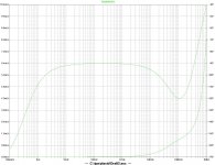
Paul: just wondering if you have any specific thoughts on the Placid after seeing the simulated output impedance?
Somehow I missed those plots. Where are they?
Paul, Allen, I don't have a product, but you guys are more than welcome to comment on the shunt regulator I'm working on. With respect to one of your earlier comments about using a cascode in the CCS, how much of an improvement did you notice?
Somehow I missed those plots. Where are they?
Post 11, just above: http://www.diyaudio.com/forums/powe...unt-regulated-power-supply-2.html#post1964018
Hi Russ,
I didn't mean to appear patronising, sorry.
I see more questions are on the horizon from enthusiasts. I will keep it constructive but please understand that I may have to decline to answer some questions due to the non-disclosure issues I mentioned earlier. I may only be able to indicate a trend rather than give an actual example.
Hi Beefy,
I do not use simulators but prefer realtime measurement and testing as well as listening to the results in any trials I do. As Russ mentioned, simulations can be a little optomistic compared to actual measurements because actual layout, wiring etc can have profound influence on the final result.
Hi ikoflexer,
Cascoding a current source tends to increase the current source impedance considerably over a wider bandwidth. This is usually beneficial with a shunt regulator as the supply rejection is governed by the ratio of the current source impedance to the shunt element impedance. The higher the ratio the better.
Regards
Paul
Paul,
Everything is fine. No worries. As long as the conversation remains constructive and respectful I am happy to continue it.
I did actually test the real output Z of the Placid using a power amplifier to create 20ma peak sine and square wave loads. I then used an instrumentation amp with 30db gain to look at the error voltage. It was virtually undetectable until about 20khz.
based on my calculations the output Z is very close to the plot posted. Still I would be more than happy if someone with more skill and better gear then I have wanted to measure the thing.
Cheers!
Russ
Hi ikoflexer,
Cascoding a current source tends to increase the current source impedance considerably over a wider bandwidth. This is usually beneficial with a shunt regulator as the supply rejection is governed by the ratio of the current source impedance to the shunt element impedance. The higher the ratio the better.
Regards
Paul
Yes, you've said this before. In my design I have not experienced a large improvement. Anyway, I sense that the conversation is kept about general principles and specifics are somewhat avoided here, so we'll leave it at that. Thanks.
- Status
- This old topic is closed. If you want to reopen this topic, contact a moderator using the "Report Post" button.
- Home
- Amplifiers
- Power Supplies
- CCS in Placid-BP Bipolar Shunt Regulated Power Supply