Yes. +/-12.5V. It has been working very well. When I first soldered the 0.1uF between the rails, the negative rail only went up to 9.5VDC and positive rail 11.5VDC. I then replaced the 0.01uF, the negative rail went up to 9VDC and positive rail 11VDC. Put the scope probe on the rails, saw graphs jumping all over the place. Removed the cap, it was measured very quiet. Turn on the music, Wow, very nice.
I can imagine the two regs playing tug-of-war with each other.
But it works OK with 0.1uF from each rail to GND right? Stability for the price of an extra cap. I say it's worth it.
This idea has come up before, I now recall, and it oscillated wildly even in the simulator. I forgot about it.
But it works OK with 0.1uF from each rail to GND right? Stability for the price of an extra cap. I say it's worth it.
This idea has come up before, I now recall, and it oscillated wildly even in the simulator. I forgot about it.
I have a few RF chokes up to 470uH sitting on the shelf that can be used.
But your regulator has already some 160dB plus ripple rejection, why bother?
My LCLC raw supply would have got rid of all high frequency junks.
Bill,
May I ask what values you use for your LCLC? How did you arrive at the values?
Thanks,
Ken
Bill,
May I ask what values you use for your LCLC? How did you arrive at the values?
Thanks,
Ken
I used two programs: 1) Duncan's PSUII. This program gives you an accurate modelling of the power supply from the Transformer, bridge to the CLR filters. It calculates the RC constants, voltage, current and power dissipation at each stage (hence you work out the power rating of your components) and let you see the rectified and smoothed ripples according to your CLR filters. 2) LTSpice. I modelled the LCLC filter with LTSpice to see how much ripple rejection at various frequencies.
The chokes I used are RF chokes. I consider them to be good. Normal LCLC filters use much larger chokes than the ones I have. But remember the regulators we use here have very high ripple rejections, especially at lower frequencies. Actually, most regulators are very good at rejecting ripples at lower frequencies, only poor at higher frequencies. So my idea is to use capacitor for low frequency smoothing, and RF chokes for high frequency filtering. With smaller chokes, the price is low (I paid no more than $2 each for some very good quality 470uH 3A rated), size is small, easy to fit.
In the schematic below, the resistor is 4.7R. It can be anything from 1R up. Don't use anything less than 0.5R to 1R, because you need the resistance for damping. To high value will drop the voltage too much and produce heat.
As you can see, with this LCLC, I can achieve over 143dB at 20kHz, and 186dB above 1MHz. Of course, in real life, parasitic capacitance will reduce that figure. But it is still VERY VERY good.
By the way, you don't need to use the same values. I happened to have the components with those values. For example, the 3,300uF are the Panasonic FC 35V caps I had on hands.
An externally hosted image should be here but it was not working when we last tested it.
Last edited:
@ikoflexer: when do you think we are going to see a PCB to buy?
One day not too far from now.
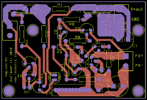
Positive rail pcb layout finished again and done from scratch after the schematic was modified; please have a look and comment. Double layer, 3x2 inches, pads, GND and power traces on both sides, signal traces only on copper side.
You will see the V+out connector is right next to the mosfet, which will interfere with using those tiny wrap-around heat sinks. The idea is to have the distance between M1 drain to the V+out connector as short as possible. A flat heat sink that extends from M2 to M1 will be best for this; another possibility is the case side wall. The mosfets can also be mounted horizontally and attached to the bottom of the case.
There are thick traces where it matters, and a blob for GND. There is no ground in and ground out. The best here is to run a thick wire from the regulator ground to star ground.
The negative layer needs to be done from scratch. Argh
It would look nicer, but the board would have to be longer, or taller. If it'd be taller, then it would be impossible to mount the mosfets to a large adjacent heat sink. If it would be longer, it would increase the distance on the V+out side to the load. To me it's better to have these technical advantages with a few points lost on good looks or symmetry.
I'm sure everyone who was hoping to get these boards is tired of waiting, so I publicly apologize again. There are too many things on my plate at the moment and just can't deal with organizing a group buy. So sorry, but that's life, full of dirty diapers (in my case, literally). The group buy is put on hold for whatever time it takes me to finish everything. If I order the pcb I'll make an announcement and whoever wants can get some. Until mid July I'll be gasping for air.
There is one piece of good news though. I've compared the regulator noise with the self-noise at the output of a simple one stage low noise preamp. The preamp uses four paralleled matched 2sk170v and is powered by 24v batteries, enclosed in a metal box, with the input shorted (or shorted by a 50 ohms resistor). In theory this should be well below 1nV/rtHz. Well, the noise as measured with my Fluke 8920A true rms voltmeter was lower for the regulator. I can't give absolute figures because I don't trust them anyway, but as a relative measurement, it certainly says something.
There is one piece of good news though. I've compared the regulator noise with the self-noise at the output of a simple one stage low noise preamp. The preamp uses four paralleled matched 2sk170v and is powered by 24v batteries, enclosed in a metal box, with the input shorted (or shorted by a 50 ohms resistor). In theory this should be well below 1nV/rtHz. Well, the noise as measured with my Fluke 8920A true rms voltmeter was lower for the regulator. I can't give absolute figures because I don't trust them anyway, but as a relative measurement, it certainly says something.
agree.
let s thanks the lord for giving us IKOFLEXER instead!
Huh? I'm not sure what you're trying to say. What is it today, open season on poor little me?
Guys, the schematic is there, I've discussed it in detail over and over, even posted the layout of the board. I mean... do it p2p, it's more fun anyway.
lol.
no seriously i m dead serious! well...not as dead as your poor littleavatar will be soon
on a real serious note, yes P2P can make yourself proud.
just one question if i m allowed:
within what voltage range should it work ok?
is +3.3v good and at least +-24V?
also(if i m not pushing my luck),do you have a schematic for the negative version?
Hey, technical questions are most welcome. The 5k schematic will work just fine at 24V. For 3.3V there are a couple of mods that you'd need to do, and then it's fine. I'll post details if anyone is in need. I'll post a negative 5k in the next few days. It should be pretty clear how to get the negative version, if you look at 5d. Sort of turn it upside down and reversed, in a way
ok thanks
is 24 the absolute max that you know it ll work well? because my amp i want to feed requires a minimum of +-24v. and a bit more voltage would be most welcome if it doesnt compromise performance.
also, i d like to have details for 3.3v output if possible
i ll be waiting for the negative version
is 24 the absolute max that you know it ll work well? because my amp i want to feed requires a minimum of +-24v. and a bit more voltage would be most welcome if it doesnt compromise performance.
also, i d like to have details for 3.3v output if possible
i ll be waiting for the negative version
- Status
- This old topic is closed. If you want to reopen this topic, contact a moderator using the "Report Post" button.
- Home
- Amplifiers
- Power Supplies
- My take on a discrete shunt voltage regulator