Hello,
I've just ordered three Mezmerize boards from the store, one for a DCB1 linestage, the other two in order to feed a Pearl Two phono.
Need now to size the psu parts. I'd like to use R-core trafos from Selectronic. I've read that their actual Vout is something higher than the specs, about 10%.
Since the Pearl2 needs 24V, and following the formula on the first post here, what's the better trafo choice: 2x21V or 2x24V ?
On the Pearl2 thread, Tea-Bag gave me the advice of splitting the psu by placing trafo+rectifiers+caps on a separate enclosure, and the regulator boards near the riaa boards. In this case, should I leave the Mezmerize onboard 4700uF in place?
I mean, filtering caps on both ends of the umbilical, or only near the trafo/bridge ?
Last question") Do the current Mezmerize boards require the "jfet leg trick" or not ?
Do the current Mezmerize boards require the "jfet leg trick" or not ?
Thanks a lot in advance. Carlo.
I've just ordered three Mezmerize boards from the store, one for a DCB1 linestage, the other two in order to feed a Pearl Two phono.
Need now to size the psu parts. I'd like to use R-core trafos from Selectronic. I've read that their actual Vout is something higher than the specs, about 10%.
Since the Pearl2 needs 24V, and following the formula on the first post here, what's the better trafo choice: 2x21V or 2x24V ?
On the Pearl2 thread, Tea-Bag gave me the advice of splitting the psu by placing trafo+rectifiers+caps on a separate enclosure, and the regulator boards near the riaa boards. In this case, should I leave the Mezmerize onboard 4700uF in place?
I mean, filtering caps on both ends of the umbilical, or only near the trafo/bridge ?
Last question
Do the current Mezmerize boards require the "jfet leg trick" or not ?Thanks a lot in advance. Carlo.
With the above trafo I built an external PSU, using MUR820 diodes and CRCRC filter.-Use 2x24VAC.
Its output is about 36V per rail (with no load).
My 2sk170BLs' Idss is about 10,8mA.
I've bought a bag of 593-VAOL-3HCE4 yellow leds (from Mez BOM). Using a 9V battery and a jfet for measuring, I'm getting 1.96V to 1.97V.
Am I good to go with these components ?
My board is a Mezmerize, and the goal is +/-24V 200mA, to feed a Pearl Two channel.
Thanks!
Your parts and DC input are good enough. Now go through the post#1 steps for +/- 24V. Allow for enough extra mA above the Pearl two channel consumption regarding your sinking. If there is no published figure, use 1 Ohm in series with +/- to Pearl with any 24V DC PSU, measure the voltage drop over 1 Ohm and calculate. Or put an Ameter inline to Pearl.
P.S. The CRCRC thing will need adjustment for not having under 34VDCin under final load. You got to know where your CCS will be first is even more imperative than just allowing a "quality" spare current.
Thank you Salas for ultrafast answer
So, once the shunt circuit is completed, I'll attach to it the external PSU and, if the input voltage doesn't drop under 34VDC, I'll tweak the filter accordingly. Right ?
About the CCS amperage, should we aim for a total current let's say double the load requirements, or something to keep the mosfets warm ?
I mean, sound improvement is to be expected when we have a certain amount of dissipation or when the mosfets themselves reach a target temp ?
This to avoid excess of sinking.
This is something I'd like to know for class A power amps too: better sound is a matter of high bias only, or actual temperature of the output devices ?
bye. Carlo.
1. Yes. You will use either a dummy or the real load to the reg and you will apply the DCin PSU to the reg. If the CCS demand drops the DCin PSU under 34 min 32V, readjust the RC elements for smaller drops.
2,3,4. +150mA from load demand is a good conservative figure. If your MOSFET sinking allows you may add double that to get an audible plus.
5. In our case more current means more transconductance from the big MOSFETS as in CLASS A amps, but not to extract more AC domain linearity. It is to flatten out and minimize the regulator's output impedance across the audio band and beyond. More current damping. That thing is a benefit since the audio circuit is always closing the power loop through its PSU. Sideways benefit in other words.
Temperature is a byproduct, a linear electronics efficiency % problem. There is a zero temperature coefficient zone we would like to stay but our VMOSFETS have it way too high for current. 1.5-3A.
They are still OK enough in our region the way we put them to work nonetheless.
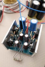
Finished my first regulator. With a 220R test resistor I'm getting Vout=6.96V, and 1.94V across the test R itself. Dummy load is 800R on each rail.
Replaced test R with 2k2 on both rails. I'm now getting Vout=+/-22.4V.
Vin dropped to about 32.4V per rail.
With 2x22.1R and small sinks (75*30*4mm) the temperature on IRF cases reached about 65C (149F).
The yellow leds are happy and shiny
Going to raise the current to at least 300mA, with finned sinks, and trim the V resistor once the actual Pearl Two channel is completed.
What a nice toy Salas! thanks a lot for sharing this idea.
Attachments
Hooked one Pearl2 channel to the regulator, with 3x22.1R and bigger sinks.
Looks like the phono card is asking for about 40mA on each rail.
Across 3x22.1R I'm reading 1.96V on the plus side, and 1.76 on minus.
So, the current dissipated by the mosfets is >200mA per side.
The current mosfet on the minus rail is sensibly hotter than its + brother.
Everything looks stable, no unexpected heat, smoke or fireworks
Now, time to complete the second channel and fight against hum&buzz.
Hi Siberia,
you mean the turntable ?
I've just restored my beloved Thorens TD125Mk2, bought it some 35 years ago..
The motor wasn't spinning anymore, it was enough to replace a couple of 1000uF caps,
a common fault with this table.
My plan is to build a new plinth and replace the old tonearm with a Jelco 750, and maybe a Dynavector cartridge in place of the venerable Stanton 681.
I do not see an answer. In the store I only see Mesmerize boards. What about pdf of boards to make my own? I have seen a variety in different posts, but am not sure which pdf design is the same as the hypnotize boards.Are these PCBs still available ??
OK, I shanghaied this quote to post my question.Your parts and DC input are good enough.
I am thinking of using this design for both a pre-amp and a crossover based on the B-1 topology, so I am looking at powering about 10 B-1 'modules' per side. If a complete B-1 draws 20mA (stereo), then I should be drawing about 200mA. To be safe I should double that and design for 400mA, yes? Also, I have a good source of pure DC @ 50V. With a voltage divider I can get +/- 25VDC. What happens if I put 25V in for 10V out (instead of +7V)? Should I use a series regulator first to drop V to 17 or so?
Thanks for the help.
Yes, double current capacity is good. With 15V Vin-Vout dif VS 7V you get more dissipation on the CCS MOSFET but better CCS PSRR frequency because the MOSFET levels out for capacitive parasitics at that VDS. There is the hot-rod Hypnotize DCB1 successor board and the BIB regulator board still in periodic circulation that you can use.
I do not see them in the store. Where/how do I get them? Is there a 'sign up'?There is the hot-rod Hypnotize DCB1 successor board and the BIB regulator board still in periodic circulation that you can use.
I only looked in store.See in the group buys section.
Thanks
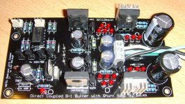
Gentlemen, a DIY-friend of mine left me his partially built "Direct Coupled B1-Buffer with Shunt Regulator" - see attached image.
For example: he has already soldered all of the 2SK170 transistors.
I have finished the PCB yesterday and did some measurements / tests. The transformer used is a 2x12VAC / 50VA toroid.
All LEDs are shining and no component is getting hot.
But:
1st: I had troubles with the relay. It would not switch on. I finally replaced the BC550 (the upper one) by a 5V1 - ZENER - diode. Now the relay switches on after about 4-5 seconds.
2nd: I measured the positive rail-voltage (10.5V) and the negative rail-voltage (9.5V !). So there is > 1V difference. Is this tolerable?
I have measured and selected the LED-strings by myself. They are definitely o.k.
3rd: I measured 1mV DC-offset (I have measured between Output and GND) on one channel and 10mv (!) on the other channel.
Is this a "usable" buffer or do I need to fix anything?
Best regards - Rudi_Ratlos
Attachments
- Status
- This old topic is closed. If you want to reopen this topic, contact a moderator using the "Report Post" button.
- Home
- Amplifiers
- Power Supplies
- Using the HYPNOTIZE as a general shunt reg PCB