")
It's almost blasfemy cutting up those hypnotize boards.
They do a great job feeding my B2 dac !
Nope, I dont think so. This is DIY. Looks great.
My DAC sounded a little to much in my face, so I changed the DCB1 Schottky's to HFA08TB60 Ultrafast, Soft Recovery diodes. I also changed the Wima 0,22uF's with small Obbligato's 1uF-2uF. That last mod changed the sound a lot in the prefered direction.
Never thought that a filter cap on that place would have such an impact.
Never thought that a filter cap on that place would have such an impact.
Fran had done some substitutions in types back in the days before the blue release if I remember well, and we decided the Wima 0.22u as a standard but we gave space on PCB and encouraged both value and type experiments if something could stick better to individual system/preference. Yes its influential as a position.
Yes, i did read that in the manual for the BiB shunt. But with more uF the sound from a certain cap ( Obbligato in my case) will also be stronger present in the music, maybe too much. I want to adjust the sound, for me that's even more important than have the best filtering. This adjusting to optimal will take a lot of time.
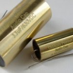
The surface is varnished, but the layer is very thin. Maybe I can use a wire on a cleaned part of the cap and then use schrinking tube to isolate the cap.
The wires of the cap can also touch the copper tube, so isolating is a good thing here.
The surface is varnished, but the layer is very thin. Maybe I can use a wire on a cleaned part of the cap and then use schrinking tube to isolate the cap.
The wires of the cap can also touch the copper tube, so isolating is a good thing here.
Salas,
You give an explanation on how to figure numbers but is there a link to a description of how the circuit functions. I think I have a general understanding, but would like to know more specifically how it all works. Only shunt regulated article I can find is Jungs differential version.
You give an explanation on how to figure numbers but is there a link to a description of how the circuit functions. I think I have a general understanding, but would like to know more specifically how it all works. Only shunt regulated article I can find is Jungs differential version.
I had written several times in the threads. In general the input section consists of a Mosfet constant current source held open steadily by the leds and a resistor fixes its current. A jfet ccs makes the leds even steadier. That is to insulate the regulator from the rectification in both directions. The voltage reference is made up by the more leds, again Jfet ccsed. That reference the bjt compares to the output and gives correction signal to the shunt output mosfet. The bjt has another ccs for load than just a resistor. Increases its efficiency. What current is extra to consumption and coming from the main Mosfet CCS is shunted to ground keeping the shunt Mosfet low impedance. That's about it.
Thanks. I am new to BJT's, only using fets up to this point, and wasn't totally sure if this was the control mechanism. I also found DougL's writeup in the wiki. I noticed that in the BiB, you switched to the 117 vs 170, would the performance gain be similar in this setup?
- Status
- This old topic is closed. If you want to reopen this topic, contact a moderator using the "Report Post" button.
- Home
- Amplifiers
- Power Supplies
- Using the HYPNOTIZE as a general shunt reg PCB