Given the interest of many DCB1S GB participants in exploiting the HYPNOTIZE board as a shunt regulator only, here is a guide of how it can be done properly. You can start exchanging experience and showing builds in this thread after the boards will be delivered to you. Avoid to post reg only related stuff in the DCB1S HYPNOTIZE & MEZMERIZE thread. Lets keep it organized right from the start.
A. Overview
The Hypnotize board's regs part was made to cater for the DCB1S needs. It does not have specially designed layout so to make it easy for a general regulator use, like accepting different sizes of capacitors, variable voltage on the fly, etc. On the other hand, its compact, spread by the GB, and can make do. Lets see how.
B. Step by step guide
Specs
It can be set from +/-5V to +/- 35V. 100mA to 1A per side. Two things govern the setting. One is the 5 leds Vref pads area. Those are for setting the voltage. The parallel resistor positions next to the main filter capacitors marked as 2x 68R, are to set the amperage of the constant current source part of the regs. The 1A limit is due to the size of the bridge rectifier diodes acceptable by the board. The +/-V limits are due to the specific TO-92 semiconductors max.
1. Setting the voltage
Know your voltage and current targets. Use a power transformer capable of 7V more than that Vout target after rectification, and 2 times the total target CCS current. Read about setting the main CCS current first, below in the text.
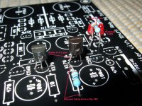
See the attached picture. It shows one side, the positive one. For the negative side you do the same, except one special move you have to do on the positive side considering its Vref JFET. You have to stuff the whole regs part of the board before you set, but the components of interest are shown only, for clarity.
In the Vref pads part you have to insert the two 3mm 1.8-2Vf leds shown. Red green or yellow generic leds are adequate. You put them ONLY in the shown positions. You also install a TEST 220R 1/4W resistor next to them in the specific position shown. You install it high as in the picture, the legs are going to be useful later on.
The positive side JFET MUST be installed with the two far legs only soldered to the PCB. The middle one is bent and soldered to the one on to its left as from the back, off board. The 1st picture is tell tale. So Drain and Source go in the PCB, when Gate is becoming one with the Source pin. You can prepare that before soldering the particular 2SK170BL to the PCB. Cut off the excess Gate pin length. THIS IS NOT APPLICABLE WHEN THE HYPNOTIZE IS FULLY STUFFED USED AS A BUFFER. THE JFET GOES IN NORMALLY THEN. **Also don't do the leg trick if with a BLUE Hypnotize board even if used as PSU only. Insert parts normally, and use the 100uF not the PP 0.22uF.
The negative side 2SK170BL goes in the PCB 3 legs normally, as it can be seen in the picture.
After the regs are fully populated and powered, you measure the voltage drop across the 10R resistors. I=V/R and that derives the current through each Vref for the particular JFETs and transistors to your build. Note that current (few mA) for each side.
Measure the +/- Vout. Note the voltages.
Measure the voltage across each side's test resistors. Note the voltages.
Vout total is comprised from the2 leds forward voltage drop, the test resistor's voltage drop due to the constant current provided by the mentioned JFETs, plus the Vbe of the 550/560 transistors that the Vref sits on (about 0.66V).
So, if you subtract the test resistor's voltage from the total Vout, you know your base. The resistor choice is the main part and the one you are going to set to your target with. Target Vout=base voltage + resistor voltage.
For low voltages near 5V, it may result to be just a small resistor for matching mainly since the leds+Vbe are providing near there anyway.
Now remember you noted the current through the 10Rs? Resistor voltage=VrefCurrent x resistor value.
Power it off. Clip off the test resistors up high so to leave enough pins length off board. Install Appropriate resistors on those legs, high enough off board for proper ventilation and ease of access for changing Vout or trimming values. Use 1W resistors if targeting over +/- 20Vout.
2. Setting the current
ICCS=2.2V/Rset (has tolerance due to many factors 1.6-2.2V usually). Choose 2 parallel 1W resistors for each side to install in the marked 2x 68R positions. Their total value in parallel when used in the above simple formula, must result to an ICCS current, roughly double of your powered circuit's constant consumption per voltage polarity side. That will give ample dynamics and better sonics.
3. Sinking
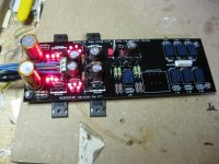
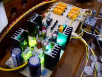
There are two methods. One is to mount the Mosfets underneath PCB like in the 2nd picture and bolt them against a wide sink or thick metal box, or use individual sinks when having the Mosfets upright like in the 3rd pic. Depends on the current and voltage levels, consequently the heat you produce, and of course on your build's mounting specifics.
The heat dissipated is the voltage across each Mosfet times the current it passes. The shunt Mosfets (last ones to the left near audio part) are dissipating Vout X current not used by the load. The CCS mosfets (the ones near the main capacitors) are dissipating Vdiff X total current. Vdiff is the difference between voltage value after rectification and RegVout. Keep that no less than 7V by choosing an appropriate power transformer as noted early in the text.
4. Example
I want to make a +/-15V shunt reg for my preamp. Its steady state consumption is +/- 75mA. I have this oddly named pitch black board after some American Armenian NuMetal band's song that I got on a GB from some Tea-Bag named guy. What the **** do I have to do? I like Cher's see through dressed videos, don't care about SOAD, but beyond that I am clueless.
Take it easy. Read all the above text. Choose trafo. Choose (7mm lead spacing) main capacitors voltage that can take it after x 1.41. Install two matched leds and 220R test resistors per side as in the pic. Fully stuff the regs part of the thing. Use 2x 33R 1W resistors in the 2x 68R places. Good for about double the needed given the 2.2V/Rset (33//33=16.5R) ballpark formula you read before. Sink it USING silicone TO-247 insulation pads. Power it up.
Say you measure 70mV on the 10Rs and 6.14V out. You measure about 1.54V across the test resistors. 6.14-1.54=4.6V, its your base voltage, can't go lower. 15V-4.6V=10.4V. You need to add that part. Power it off now. Cut off the 220Rs up near the body. Toss 'em in the bin. OK. 70mV/10R=7mA. That is how much it runs in the Vrefs with those Idss matched JFETS per side that you had. 10.4V/7mA=1.486kOhm. 1.5k 1/4W will do. Install them on those left off test resistor PCB proud pins. Power on again. OK. +/- 15.1V @ 133mA CCS all set. If one side had weaker mV on its 10R or the vbe and Vfs were a bit unmatched, then use a small corrective resistor in series with the main 1.5k on the weak reg's side, so to match +/- Vouts. Connect your pre to it. Hey, the shunt Mosfets are running cooler now, must be sharing half the current with the load. Listen...hmmm compared to that LM317/337 you had, maybe you can ''feel more detail in music''. Naah, you can't?. Swear at Salas, Crt, and Tea-Bag that put you in the drag then. If else...Enjoy.
A. Overview
The Hypnotize board's regs part was made to cater for the DCB1S needs. It does not have specially designed layout so to make it easy for a general regulator use, like accepting different sizes of capacitors, variable voltage on the fly, etc. On the other hand, its compact, spread by the GB, and can make do. Lets see how.
B. Step by step guide
Specs
It can be set from +/-5V to +/- 35V. 100mA to 1A per side. Two things govern the setting. One is the 5 leds Vref pads area. Those are for setting the voltage. The parallel resistor positions next to the main filter capacitors marked as 2x 68R, are to set the amperage of the constant current source part of the regs. The 1A limit is due to the size of the bridge rectifier diodes acceptable by the board. The +/-V limits are due to the specific TO-92 semiconductors max.
1. Setting the voltage
Know your voltage and current targets. Use a power transformer capable of 7V more than that Vout target after rectification, and 2 times the total target CCS current. Read about setting the main CCS current first, below in the text.
See the attached picture. It shows one side, the positive one. For the negative side you do the same, except one special move you have to do on the positive side considering its Vref JFET. You have to stuff the whole regs part of the board before you set, but the components of interest are shown only, for clarity.
In the Vref pads part you have to insert the two 3mm 1.8-2Vf leds shown. Red green or yellow generic leds are adequate. You put them ONLY in the shown positions. You also install a TEST 220R 1/4W resistor next to them in the specific position shown. You install it high as in the picture, the legs are going to be useful later on.
The positive side JFET MUST be installed with the two far legs only soldered to the PCB. The middle one is bent and soldered to the one on to its left as from the back, off board. The 1st picture is tell tale. So Drain and Source go in the PCB, when Gate is becoming one with the Source pin. You can prepare that before soldering the particular 2SK170BL to the PCB. Cut off the excess Gate pin length. THIS IS NOT APPLICABLE WHEN THE HYPNOTIZE IS FULLY STUFFED USED AS A BUFFER. THE JFET GOES IN NORMALLY THEN. **Also don't do the leg trick if with a BLUE Hypnotize board even if used as PSU only. Insert parts normally, and use the 100uF not the PP 0.22uF.
The negative side 2SK170BL goes in the PCB 3 legs normally, as it can be seen in the picture.
After the regs are fully populated and powered, you measure the voltage drop across the 10R resistors. I=V/R and that derives the current through each Vref for the particular JFETs and transistors to your build. Note that current (few mA) for each side.
Measure the +/- Vout. Note the voltages.
Measure the voltage across each side's test resistors. Note the voltages.
Vout total is comprised from the2 leds forward voltage drop, the test resistor's voltage drop due to the constant current provided by the mentioned JFETs, plus the Vbe of the 550/560 transistors that the Vref sits on (about 0.66V).
So, if you subtract the test resistor's voltage from the total Vout, you know your base. The resistor choice is the main part and the one you are going to set to your target with. Target Vout=base voltage + resistor voltage.
For low voltages near 5V, it may result to be just a small resistor for matching mainly since the leds+Vbe are providing near there anyway.
Now remember you noted the current through the 10Rs? Resistor voltage=VrefCurrent x resistor value.
Power it off. Clip off the test resistors up high so to leave enough pins length off board. Install Appropriate resistors on those legs, high enough off board for proper ventilation and ease of access for changing Vout or trimming values. Use 1W resistors if targeting over +/- 20Vout.
2. Setting the current
ICCS=2.2V/Rset (has tolerance due to many factors 1.6-2.2V usually). Choose 2 parallel 1W resistors for each side to install in the marked 2x 68R positions. Their total value in parallel when used in the above simple formula, must result to an ICCS current, roughly double of your powered circuit's constant consumption per voltage polarity side. That will give ample dynamics and better sonics.
3. Sinking
There are two methods. One is to mount the Mosfets underneath PCB like in the 2nd picture and bolt them against a wide sink or thick metal box, or use individual sinks when having the Mosfets upright like in the 3rd pic. Depends on the current and voltage levels, consequently the heat you produce, and of course on your build's mounting specifics.
The heat dissipated is the voltage across each Mosfet times the current it passes. The shunt Mosfets (last ones to the left near audio part) are dissipating Vout X current not used by the load. The CCS mosfets (the ones near the main capacitors) are dissipating Vdiff X total current. Vdiff is the difference between voltage value after rectification and RegVout. Keep that no less than 7V by choosing an appropriate power transformer as noted early in the text.
4. Example
I want to make a +/-15V shunt reg for my preamp. Its steady state consumption is +/- 75mA. I have this oddly named pitch black board after some American Armenian NuMetal band's song that I got on a GB from some Tea-Bag named guy. What the **** do I have to do?
I like Cher's see through dressed videos, don't care about SOAD, but beyond that I am clueless.Take it easy. Read all the above text. Choose trafo. Choose (7mm lead spacing) main capacitors voltage that can take it after x 1.41. Install two matched leds and 220R test resistors per side as in the pic. Fully stuff the regs part of the thing. Use 2x 33R 1W resistors in the 2x 68R places. Good for about double the needed given the 2.2V/Rset (33//33=16.5R) ballpark formula you read before. Sink it USING silicone TO-247 insulation pads. Power it up.
Say you measure 70mV on the 10Rs and 6.14V out. You measure about 1.54V across the test resistors. 6.14-1.54=4.6V, its your base voltage, can't go lower. 15V-4.6V=10.4V. You need to add that part. Power it off now. Cut off the 220Rs up near the body. Toss 'em in the bin. OK. 70mV/10R=7mA. That is how much it runs in the Vrefs with those Idss matched JFETS per side that you had. 10.4V/7mA=1.486kOhm. 1.5k 1/4W will do. Install them on those left off test resistor PCB proud pins. Power on again. OK. +/- 15.1V @ 133mA CCS all set. If one side had weaker mV on its 10R or the vbe and Vfs were a bit unmatched, then use a small corrective resistor in series with the main 1.5k on the weak reg's side, so to match +/- Vouts. Connect your pre to it. Hey, the shunt Mosfets are running cooler now, must be sharing half the current with the load. Listen...hmmm compared to that LM317/337 you had, maybe you can ''feel more detail in music''. Naah, you can't?. Swear at Salas, Crt, and Tea-Bag that put you in the drag then.
If else...Enjoy.Attachments
The 1A limit is due to the size of the bridge rectifier diodes acceptable by the board.
Thanks Salas, I appreciate the support you are putting into this board! A quick question, can I use the positive reg side of this PCB to power a Tripath TA2020, say 2A or 2.5A @ 13V, if I use an external diode bridge and just feed the DC to the PCB?
Ian.


Salas, for a T-amp, here's a test run according to what you wrote.
past research - http://www.diyaudio.com/forums/powe...w-voltage-shunt-regulator-83.html#post1889990
The plan:
First to set the CCS - I want 2.5A max, and most of the time it will be less than 500mA, we set the current for the CCS to 2.5A (from the research link). So Rset = 2.2/ICCS = 2.2/2.5 = 0.88 ohms. Power dissipated is 2.2V x 2.5A = 5.5W. So I choose 2 x 1.8 ohm 10W resistors for Rset. Or one of these 25W resistors available in 0.82 ohm or 1 ohm:
Arcol | Passives | Resistors, Potentiometers or Control Knobs | Resistors, Fixed Discrete | Aluminium Housed, Wirewound -10 to 600W |HS25 R82 J
Second, I need a power transformer capable of delivering approx 20 to 25V DC at say 4 amps, say a 100VA transformer? Is that big enough?
Third is setting the voltage, you made that very clear in your post #1 so no problems with that.
Fourth is the heatsink - from the research link, it's going to have to be 0.5C/W (quite a big one) and sink at least 50W - 60W. That can be done.
Am I heading in the right direction?
If you need 13Vout be conservative and don't go over 20VDCin with the transformer you are going to get. You don't need to increase the dissipation of your CCS Mosfet beyond what is needed. When in Ampere territory, we must watch heat. Also don't buy just one big resistor based on the ballpark formula, because each Mosfet can have different Vgs that also changes in large current scale. So make R1 out of a 10Wx2 combination. You have more freedom to correct your aim by measuring its Vdrop on your practical build, that way. You can also check your sound by adjusting up or down half Ampere depending on the speakers Z and how loud you drive. Because constant current is very hard on transformers, better get a 200VA one, I have seen enough losing voltage under such constant drainage.
The positive side JFET MUST be installed with the two far legs only soldered to the PCB. The middle one is bent and soldered to the one on to its left as from the back, off board. The 1st picture is tell tale. So Drain and Source go in the PCB, when Gate is becoming one with the Source pin. You can prepare that before soldering the particular 2SK170BL to the PCB. Cut off the excess Gate pin length. THIS IS NOT APPLICABLE WHEN THE HYPNOTIZE IS FULLY STUFFED USED AS A BUFFER. THE JFET GOES IN NORMALLY THEN.
The negative side 2SK170BL goes in the PCB 3 legs normally, as it can be seen in the picture.
why when you use it as buffer Is not same - after all this Is PS for 10V
If I need a positive voltage why I bother with negative side k170
In that buffer I use more +V a bit to help the audio part offset. So I run the +leds a bit harder. If you want only +V as a general reg, do only half part as in the guide. I.e. Do the particular one +side 2SK legs as I show in the picture if using the pcb as a reg(s) only, anyway.
Hi Salas!
Is this led suitable to be used in the B1 buffer?
Avago Technologies | Optoelectronics and Displays | Optoelectronics | LED | 3mm Radial Diffused |HLMP-1790
Regards,
Eddy.
Is this led suitable to be used in the B1 buffer?
Avago Technologies | Optoelectronics and Displays | Optoelectronics | LED | 3mm Radial Diffused |HLMP-1790
Regards,
Eddy.
Says typical Vf 1V8 at typical If 2mA. So it will climb Vf to about 2V when with the current we use here with circa 8mA Idss BL. About 70% of Idss @10V when under Vbe 0.6V (0.65-10Rdrop), hence 5-6mA. Of course you can use 2SK170GR there under the Leds if you have, for about 2.5-3mA final running If.
If using it for B1 its all Leds so they keep about the same Vf if you end up with say 1mA different 2SKs underneath them. If for general use as this thread is dedicated to, and using resistors for higher voltages, the difference will show more. Either a good match in the Vref Jfets (the ones in the 1st post's picture) or some difference in the resistors for matching +/-Vout then.
Hi Salas,
When I build a 2.5A 13V positive reg for a T-amp, could I use a regulated bench power supply (variable 0 to 30VDC, 5A, set it to 20V) for the DC input to save buying a 200VA transformer for testing? Will the sound suffer from using the bench supply?
Another question is, the T-amp has an on-board 4700uF cap, do I still fit the 100uF cap at the shunt regulator output on the Hypno PCB, or leave it out, or put the 4700uF cap in that place?
I have gathered together a fan-assisted heatsink, PCB and all required parts except the power tranny so am set to start building soon.
Ian.
Hi Salas,
I followed your post #1 and it all turned out fine, except that I misread the instructions for the CCS, the value calculated is for each individual resistor in the pair, not the total resistance in parallel, not to worry. I fitted a 5W 0.47R in that spot for now which gives about 1.7A for the CCS, a bit low, but I was a bit worried about how good the heatsink is. I might go for more current after I let it all burn in a bit. So far the heatsink is doing well and I can keep my hand on it, despite being a hot 33C (93F) day. Something I forgot was the 4700uF cap at the DC power input end, doh. I have some at work, and at home only 16V rated caps, so had to make do with just 1000uF on the Hypno, and the T-amp has 4700uF 16V on board, (which maybe is now redundant?).
So despite being unfinished and incomplete at this stage, how does it sound? At first it was mediocre, but after 4 or 5 hours it was a different story. Compared to the switch-mode supply I was using, which I thought was pretty good, well this one as it is now, hardly broken in and unfinished, is a definite cut above the other one. The vocals are less "in your face", there is a mellow character but also greater detail, lots more detail! The amp seems to sound a bit louder for the same volume setting on the same track. The sound is fuller or deeper, or maybe better balanced is the right word. The characteristics are similar in many ways to the proto Hypno I built. Lots of detail with no sharp edges, and a very clean sound, as if background noise has been eliminated. I've been running it about 8 hours now and its still improving.
I did try powering the amp straight from the DC bench power supply to see how much current this T-amp draws at normal listening levels. From the analogue current meter, it never hits 200mA, just flicks up a bit towards 200mA for heavy bass for example. The amp is rated around 15W/channel into 4 ohms and I use 4 ohm speakers. With 80 to 90% amplifier efficiency I guess I'm barely using a watt per channel at normal listening levels. I'm just mentioning this in case it has any bearing on the operation of this shunt reg in this type of duty.
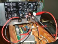
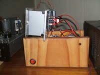
Some pics, it won't look like this when finished, I promise! It's rough, and still more things to be finalised. Its easy to swap power supplies for AB testing, takes about 20 seconds, just swap the white connector. BTW the Hypno PCB is a joy to work with, very nice indeed. Sorry for long post
pic1
pic2
pic3
pic4
I followed your post #1 and it all turned out fine, except that I misread the instructions for the CCS, the value calculated is for each individual resistor in the pair, not the total resistance in parallel, not to worry. I fitted a 5W 0.47R in that spot for now which gives about 1.7A for the CCS, a bit low, but I was a bit worried about how good the heatsink is. I might go for more current after I let it all burn in a bit. So far the heatsink is doing well and I can keep my hand on it, despite being a hot 33C (93F) day. Something I forgot was the 4700uF cap at the DC power input end, doh. I have some at work, and at home only 16V rated caps, so had to make do with just 1000uF on the Hypno, and the T-amp has 4700uF 16V on board, (which maybe is now redundant?).
So despite being unfinished and incomplete at this stage, how does it sound? At first it was mediocre, but after 4 or 5 hours it was a different story. Compared to the switch-mode supply I was using, which I thought was pretty good, well this one as it is now, hardly broken in and unfinished, is a definite cut above the other one. The vocals are less "in your face", there is a mellow character but also greater detail, lots more detail! The amp seems to sound a bit louder for the same volume setting on the same track. The sound is fuller or deeper, or maybe better balanced is the right word. The characteristics are similar in many ways to the proto Hypno I built. Lots of detail with no sharp edges, and a very clean sound, as if background noise has been eliminated. I've been running it about 8 hours now and its still improving.
I did try powering the amp straight from the DC bench power supply to see how much current this T-amp draws at normal listening levels. From the analogue current meter, it never hits 200mA, just flicks up a bit towards 200mA for heavy bass for example. The amp is rated around 15W/channel into 4 ohms and I use 4 ohm speakers. With 80 to 90% amplifier efficiency I guess I'm barely using a watt per channel at normal listening levels. I'm just mentioning this in case it has any bearing on the operation of this shunt reg in this type of duty.
Some pics, it won't look like this when finished, I promise! It's rough, and still more things to be finalised. Its easy to swap power supplies for AB testing, takes about 20 seconds, just swap the white connector. BTW the Hypno PCB is a joy to work with, very nice indeed. Sorry for long post
pic1
pic2
pic3
pic4
Attachments
- Status
- This old topic is closed. If you want to reopen this topic, contact a moderator using the "Report Post" button.
- Home
- Amplifiers
- Power Supplies
- Using the HYPNOTIZE as a general shunt reg PCB