I'm interested in making an adjustable PS that I can use for B+ supply on tube projects. This is usually done with a LR8N3 450V regulator and a TIP50 Bipolar NPN transistor. That circuit is generally good to about 100ma according to articles I have read. I'm wanting to make it as robust as I can.
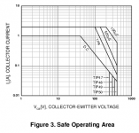
Now I'm not that sharp with solid state devices but I'd assume that the Specs of the TIP50 determine the current handling limits of the circuit. The rating are expressed as power not current. I suppose heat dissipation is the key. The TIP50G is rated for 40,000mw. So my conclusion is that I could dial down, say, a 450V B+ to 200V at 150ma and come in under the limit at 37,500mw (that's (450-200)*.150 for those without a calculator handy).
So my question is: am I thinking about this correctly? And should I be looking at the ratings of the regulator too. Perhaps it is the weak link. It has a maximum power dissapation of 740mw. How do I calculate the power the TIP50G will need at the maximum output? (I can't help but think of that as amplification factor but I suspect it's GAIN).
The next question is, should I be looking at a darlington configuration? How does that change the current capacity?
Here is a link to the TIP50G data sheet.
Thanks for the help.
Last edited:
You're running the TIP50 waaaay too close to the edge there. 40 watts is if you keep the case temp @ 25 degrees C. You're going to need moderately heroic cooling to do that. Expect it to be derated by temp (see datasheet). I don't know why you would want to throw away over 50% of your B+, you should re-think that part and start with a lower voltage. Also, you're running close to the edge on voltage as well. Personally, I like to run my devices with a high safety margin (at least 50-100%).
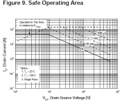
Personally, I prefer a MOSFET based regulator. It's easy to find high voltage MOSFETS with high current ratings. Look at the schematic for the PSU on Triode Guy's webpage:
http://www.triodeguy.com/Triodeguy PDF files/triodeguy_Calrad modified.pdf
It's a pretty standard design, personally I'd replace the zener string with a 10M45S set to 10ma and a resistor to get a voltage reference.
I'd use a 47N60 mosfet if I were you, as the pass element. Fairly cheap on ebay.
FCA47N60 Datasheet pdf - 600V N-Channel MOSFET - Fairchild Semiconductor
Lookup the maida regulator
Think about replacing the zener with a dn2540 ccs + pot || C as that will make it variable voltage out. You'll also want a variable current limit.
FCA47N60 Datasheet pdf - 600V N-Channel MOSFET - Fairchild Semiconductor
Lookup the maida regulator
Think about replacing the zener with a dn2540 ccs + pot || C as that will make it variable voltage out. You'll also want a variable current limit.
Attachments
Last edited:
Hi Captn Dave,
ikoflexer's suggestion is good, except for the purchase place. Always deal with proper distributors, especially is a failure would be very, very bad for you!
I'd use at least two in parallel for the pass element (mosfets). Keep in mind that you should limit the current in case your load shorts or you short the output leads. Figure worst case dissipation as your limited output current with the entire supply across the pass element(s). The entire supply means from your unregulated supply level (30 ~ 50 V above your max output voltage?). Make sure the rest of the circuit can handle that failure mode as well and you will have a robust design.
Once you figure out how much dissipation you will have, you'll understand why good supplies appear to be overbuilt.
-Chris
Thanks for your comments. I gives me plenty to think about.
I want this as a bench power supply with flexability such that I can use it to fool around with a variety of projects without having to build a power supply for each project. I don't mind throwing away B+ in that circumstance. Thanks for the Mosfet advice, that looks like the direction I will go.
I found the regulator described by Maida. I think that might be exactly what I'm looking for and I like your idea for control.
Yes, I see that is a common concern among the designs. I will be sure to incorporate that.
Thanks guys.
I don't know why you would want to throw away over 50% of your B+, you should re-think that part and start with a lower voltage.
Personally, I prefer a MOSFET based regulator.
I want this as a bench power supply with flexability such that I can use it to fool around with a variety of projects without having to build a power supply for each project. I don't mind throwing away B+ in that circumstance. Thanks for the Mosfet advice, that looks like the direction I will go.
Lookup the maida regulator
Think about replacing the zener with a dn2540 ccs + pot || C as that will make it variable voltage out. You'll also want a variable current limit.
I found the regulator described by Maida. I think that might be exactly what I'm looking for and I like your idea for control.
Keep in mind that you should limit the current in case your load shorts or you short the output leads.
Yes, I see that is a common concern among the designs. I will be sure to incorporate that.
Thanks guys.
Ah, benchtop supply. Different beast, looks and noise are no longer issues. I'd recommend paralleling MOSFET devices with big heatsinks and a fan or two. Also, a built in volt and ammeter would be mighty handy. Instead of the DN2540, I prefer the 10M45S with a variable resistor to control the CCS. You might not be able to go all the way to 450v with the 10M45 (it has a 450v limit), but it's very widely available and easy to use.
I found the regulator described by Maida. I think that might be exactly what I'm looking for and I like your idea for control.
I think you may find the reg posted on triodeguy's website (using zeners or a ccs/resistor) sounds better than a maida: a high feedback design which can sound rather strangled in comparison.
The regulation is not as tight and the output impedance is higher, but I prefer the sonics.
Ah, benchtop supply. Different beast, looks and noise are no longer issues.
Noise is an issue in my book. I don't like troubleshooting audio problems (like hum) with a noisy fan running. I have a DC power supply with a fan and it drives me nuts. I put a switch on the fan so I can shut it off. Hopefully it will fail soon so I can build or buy a new one. <END OF RANT> - Sorry
I have an old bench supply - a commercial product of some brand or other. Variable B+, plus some heater voltage. This unit is pretty old - weren't no MOSFETs when it was born. They simply used a variac in the primary.
Funny you should mention that because that's what I have rigged up now for the purpose (an old organ power supply fed from my variac - 5U4 replaced with a bridge rectifier). It works fine for most things but I'd like to build something a bit more compact and this seems like a good introduction and an excuse to learn more about regulators and SS circuits.
- Status
- This old topic is closed. If you want to reopen this topic, contact a moderator using the "Report Post" button.
- Home
- Amplifiers
- Power Supplies
- Adjustable Regulated B+ power supply question