Why not try putting a resistor in series with the opamp power leads on purpose (with decoupling caps across the power pins as usual)? I don't know how destructive a little supply impedance is. Maybe a little Zout can actually be healthy for some situations?
Or am I horribly wrong?
Regarding capacitance multipliers: the output device configuration and devices will define the bottom limit on load rejection. The capacitance must get through the impedance of these devices before it is "multiplied" into your circuit.
- keantoken
Or am I horribly wrong?
Regarding capacitance multipliers: the output device configuration and devices will define the bottom limit on load rejection. The capacitance must get through the impedance of these devices before it is "multiplied" into your circuit.
- keantoken
Last edited:
Keantoken,
Since the PSSR of the opamps are not infinite, actually they start getting less than optimal above about 1kHz, any Z in the PS introduces errors. The question may be how much error it introduces. For a maximum current of an opamp of 5mA, a 0.5R padding resistor would introduce a maximum voltage of 2.5mA if PSSR is taken out from considerations, unless the local bypass capacitor is sufficiently large and has a lower resistance. This is in a line stage and the signal will be magnified by 2 digit dB at a later stage. So I don't think any resistance padded to damp resonance is desirable, unless there are stability problems. In other words, I would choose not to use resistance in series with bypass capacitors or regulator output unless I have no other alternatives.
Regards,
Bill
Last edited:
Thank you all for contributing. After reading all your posts I have now got some ideas about the questions. It seems that the resonance beyond 3M Hertz should not cause instability problem and have no audible effects with audio.
So it was time to do some soldering. my reg output capacitor was padded a 0.5R resistor in series with a 1000uF ZL, and 0.25R was padded in series with the capacitors used in the C Multiplier. This morning I based on my modelling result and removed the series resistor from the C Multiplier, and reduced the 0.5R resistor to 0.1R and changed the capacitor from 1000uF to 2,200uF.
Obviously, the sound is subjective far less peaky at 4-6kHz which means the resonance of up to 2.5dB was removed. I can now hear only a very small broadband peak just below 2kHz. All correspond to LTSpice simulation very well. It appears that the C Multiplier does not have the damping effects as a very large capacitor.
It is a good outcome out of this discussion and I am getting much improved sound now, not just the reduced peaky sound at 5kHz. Basically, 1. I should target having no resonances within the audioband. 2. Lower PSU impedance is much better than higher impedance.
In the following two weeks I will actually measure it with an oscilliscope and a signal generator, and I will see how close my modelling is.
Keantoken, yes it makes sense to use a current source in the simulation but I don't know how to create a current source with LTSpice. If you have one, please send me a simple LTSpice asc file that contains a current source.
Best regards,
Bill
A current source is included default with LTSpice. Go into the component window and type "cu" in the search bar and you should see a circle with an arrow pointing down. That is a current source.
You can also type "lo" and it will give you the schematic symbol of a load, but this is really the exact same thing as a current source.
I personally use the "sine" option, and enter the quiescent load current as the DC offset. Then, I use, say, 1KHz as the frequency and .5 as the current, which will impose a 1A pk-pk sine on the quiescent load current. Type "AC 1" in the first AC analysis box and the simulator will use this current source in an AC analysis.
I usually use .5 as DC offset and .5 as current so as to have a sine wave that modulates from 0A to 1A.
Good luck,
- keantoken
In the 2nd half of 70ties, when Audio Magazine was alive, it published several interesting studies. One was searching for a reason why Japanese mass-produced amps sounded harsh (in these times they did) compared to audiofile models, produced in much smaller quantities. In usual terms all amps measured identical, and Otala's findings were not a problem any more.
One conclusion, confirmed by listening experiments, was that when frequencies of several MHz can reach amplifier output stages, they cause the subjective harshness to the sound. The worst range was 3 - 4 MHz.
One conclusion, confirmed by listening experiments, was that when frequencies of several MHz can reach amplifier output stages, they cause the subjective harshness to the sound. The worst range was 3 - 4 MHz.
Sounds like something to experiment with. I imagine transistors might lose some of their good DC characteristics when being in constant modulation in the MHz range.
Then again, we have much faster transistors nowadays, as opposed to 4MHz, 20MHz, etc. We have 200MHz output transistors.
- keantoken
Then again, we have much faster transistors nowadays, as opposed to 4MHz, 20MHz, etc. We have 200MHz output transistors.
- keantoken
ok, using a 7815 model actually has a different result... the current variation is 0.1A peak (which is 0.2Ap-p). you can see where the feedback begins to lose it a bit below 1k, and is completely nonexistant at 20k. if i remove the ESR from C2, yes there is a resonant peak, but there's no such thing as a cap with no ESR... the regulator doesn't behave entirely like an inductor.
Attachments
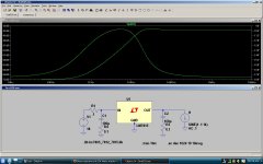
between 200hz and 20khz, yes it behaves like an inductor, but after the feedback "runs out of steam" at 20khz, it's no longer able to act inductively. so the "effective inductance" of the regulator, is only "effective" below 20khz. above 20khz, it might as well be an open circuit.
In terms of limiting the bandwidth, I have a 1kR, 220pF, 1MR right at the entrance to the circuit. Except for the high pass section for a tweeter, low pass filters come first in all other branches in a 4-way active loudspeaker. Every opamp used with any gain has a 68pF feedback resistor. I hope that is going to provide some reduction of noise / resonances at the megahertz region.
Keantoken, Thanks. I will try the CS when I have a moment.
unclejed613, thanks for your post. You reminded me of checking the lib directory and I found LT1083. Actually I will be using LT1085 and LM337, the idea adopted after reading the other current LM317 thread. Where did you get your 78XX? It would be good if I can get opa627, LT1085, LM337, LM4562.
As you can see, I am a complete novice. I may borrow this space to ask another question - how can I know if a circuit I designed is stable / functional with the opamp (opa627 and LM4562)? I am pretty sure that most stages in my active XO/EQ are fine, except a few high Q notch / Q boost filters with which I have no idea if it has enough GBW, etc. Can I check this with LTSpice?
unclejed613, good information. If above 20kHz the 3-T Reg does not behave like an inductor, any resonances at higher frequencies will mainly come from self resonance of capacitors, LCR due to parasitic capacitance, wire inductance, etc, but the resonances will be much lesser in magnitude and at much higher frequencies, not a concern with audio.
Last edited:
Type "AC 1" in the first AC analysis box and the simulator will use this current source in an AC analysis. - keantoken
Keantoken,
Thanks. I created a CS but can't find where I can put in "AC 1". I sent you a private email two days ago so you have my email address. Would you mind spending a couple of minutes creating one and sending it to me?
Regards,
Bill
join the LTSpice yahoo group. there's a lot of good library files there, as well as schematics and tons of information. that's where i got the LM78xx models from. there's also models of devices you can't find in LTSpice, such as nonlinear incandescent lamp models, spark gap models, thermistor models, vacuum tube models, etc... if it's not there, there's likely a link to a manufacturer or somebody else with a model of what you're looking for.
http://tech.groups.yahoo.com/group/LTspice/
yes you can check stability and GBW with LTSpice, just the same way you did a frequency sweep of the circuit above. when you check stability, pay attention to the phase trace as well as the gain trace. if it crosses (or even gets near)180 degrees while the gain is greater than 1, you have a stability problem. also check for steep (steeper than 6db/octave) rollofs in gain, as these indicate instability as well. GBW, same method. with an input of 1V, at whatever frequency the response trace crosses 0db, that's the GBW.
unclejed,
Thanks for your advice. I am trying to digest it. My LTSpice knowledge is really limited to what I have posted above, but no more. I don't have any EE background. My target is to design and build my 4 way active open baffle loudspeakers, and for that I am studying just sufficient materials to be able to do the active circuit design. The help from you and others are very much appreciated.
I am wondering if you (or others) could simulate the following for me, if that doesn't take long to do. That would help me to get the job done with my limited knowledge in my very limited time. If you could send me the LTSpice ASC file, I would be able to use it to simulate other circuits. The difficulty is the initial set up.
I am also attaching (linking) the ASC file.
Thanks in advance.
Regards,
Bill
http://members.optusnet.com.au/yuelo123/QBoost350Hz.asc
An externally hosted image should be here but it was not working when we last tested it.
The above is a Q boost filter I use to counter the dipole null in a large U-frame speaker. It has a 50 degree phase shift within a narrow band. The ideal opamp would work. But I don't know if it works in real life or not. I am using opa627. This filter has the highest Q comparing to most of others. So I guess that if this one works, the rest should do as well. I initially used 6n8, 1.2uF, 18k, 5.9k and 5.6k but don't like the very large size of the the 1.2uF MKP so I scale down the capacitance, hoping the increased noise is not an issue.
Last edited:
yes you can check stability and GBW with LTSpice, just the same way you did a frequency sweep of the circuit above. when you check stability, pay attention to the phase trace as well as the gain trace. if it crosses (or even gets near)180 degrees while the gain is greater than 1, you have a stability problem. also check for steep (steeper than 6db/octave) rollofs in gain, as these indicate instability as well. GBW, same method. with an input of 1V, at whatever frequency the response trace crosses 0db, that's the GBW.
This application note will further the general understanding of loop stability in linear regulators. Linear Regulators: Theory of Operation and Compensation
http://www.national.com/an/AN/AN-1148.pdf
but to implement it in the real world you need a network analyzer. (expensive, but for this purpose you don't need a multi kilo-buck hp).
I've seen the transformer replaced with an opamp in one design note published by Micrel. The difficulty with using a transformer is bandwidth limitations at both ends.
i'll have to look for it again, but there was a circuit published in EDN or Electronic Design to measure the output impedance and frequency response of linear regulators (kinda sounds like an oxymoron, but that's what we're basically discussing in this thread). it was quite a few years back, but i think i can find it again....
- Status
- This old topic is closed. If you want to reopen this topic, contact a moderator using the "Report Post" button.
- Home
- Amplifiers
- Power Supplies
- Does resonance at 1M Hertz matter for audio?