You mean like this?
http://stereophile.com/solidpoweramps/545/
Note that switching power supplies often use several smaller capacitors in parallel instead of one large one.
Advantages: Lower ESR. Lower ESL means switching harmonics are less likely to encounter impedance rise above self-resonance.
Disadvantages: Higher cost, possibly higher rate of failure.
pcb for 10x1000uF is not the same as for 1x 10.000uFSingle capacitor is smaller, but to get the capacitance needed, you put multiple caps, which, require a lot more space than the big expencive cap.
PCB cost is nothing compared to an large, expensive capacitor. To use multiple smaller cap in parallel, we need to make sure them operating in a balance manner.
Note that switching power supplies often use several smaller capacitors in parallel instead of one large one.
Advantages: Lower ESR. Lower ESL means switching harmonics are less likely to encounter impedance rise above self-resonance.
Disadvantages: Higher cost, possibly higher rate of failure.
The reason SMPS use many parallel caps are to reduce the case size and still have the same total capacitance. The smaller case size gives low esr esl closer to the switchers much higher ripple frequecies. All things being equal (which they never are for DIY) I would select the large case computer grades esp at 105 degrees for filtering 120Hz. I would then bypass them with more smaller case sizes onboard the PWB for harmonics and hash supression keeping the high charging currents away from sensitive active parts.
PCB cost is nothing compared to an large, expensive capacitor. To use multiple smaller cap in parallel, we need to make sure them operating in a balance manner.
Yes, a Panasonic document on their range of electrolytics says:
Capacitors Connected in Parallel
Circuit resistance can approximate the series
resistance of the capacitor, resulting in ripple
current load imbalances. Careful design of
wiring methods can minimize excessive ripple
currents applied to a capacitor.
Capacitors Connected in Series
Normal DC leakage current variations among
capacitors can cause voltage differences. The
use of voltage dividing sharing resistors with
consideration to leakage currents can
compensate for voltage imbalances.
I've never heard of "balancing capacitors" before! I wonder what they mean by "careful design of wiring". I was thinking of mounting a bunch of caps on a double sided copper-clad PCB - top plane = (+), bottom plane = (-).
To clarify my thoughts: I was not necessarily talking about SMPS (should've stated that). I am thinking more about the large resevoir caps used in Mains-> Transformer -> bridge rectifier -> large smoothing Cap type (standard) power supplies classically used in Pre-Amps and Power Amps.
To reword my question:
I have a solid state amplifier (an Arcam Alpha II) - It uses two large smoothing caps in the supply, (6,800uF 35V). If I wanted to improve the design of the PSU stage, would one suggest just bunging in some larger, better (more expensive) caps OR paralelling up many good ones (a bunch of Rubycon ZL's for example)????
Cheers,
Andy
Just stick with the large singles. You can buy higher quality by upgrading the temp. range from 85 to 105, resulting in lower esr and longer life. You should stay with the same cap value maybe 20%-40% more. If you go much larger than designed without upgrading rectifiers and bigger transformer you will not see any improvement really. Akis brings up a really important part about parallel wiring, just using PWB ground planes is NOT a good idea. In engineering, properly changing one thing w/o considering all the angles, usually just results in other problems not improvement.
For pre-amp or low current consumption applications, a RC filter is more effective and cheaper than using a larger cap. An additional resistor together with the cap forms a RC low-pass filter.
As pointed by infinia, larger cap (single or parallel) can introduce new problems. It can create a very high inrush current which may burn the mains input fuse.
As pointed by infinia, larger cap (single or parallel) can introduce new problems. It can create a very high inrush current which may burn the mains input fuse.
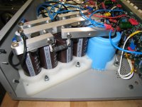
When I upgraded the PS in my amp, I added 4x15,000uF (from Apex Jr at $3 each, so cheap 'surplus' caps) to the existing 23,000uF on each rail, separated into a CRC with a 0R25. I also used a larger transformer. The amp already had a thermistor for inrush protection, and I haven't had any problems. PS ripple went from 15mV to under 4mV, and bass authority is amazing even at normal volumes.
Attachments
Great replies, thanks so far...
I understand that increasing capacitance = increased inrush etc etc.
going back to infinia's reply if I may:
Cheers,
Andy
I understand that increasing capacitance = increased inrush etc etc.
going back to infinia's reply if I may:
OK, enlighten me: why is using planes NOT a good idea?Akis brings up a really important part about parallel wiring, just using PWB ground planes is NOT a good idea
Ain't that the truth!In engineering, properly changing one thing w/o considering all the angles, usually just results in other problems not improvement.
Cheers,
Andy
I was saying about pcb size, not price. Will the pcb fit in the case?PCB cost is nothing compared to an large, expensive capacitor. To use multiple smaller cap in parallel, we need to make sure them operating in a balance manner.
If he has big case, he can use big tall caps with no problem, but if the case is small...
 i will go for big ones.
I was saying about pcb size, not price. Will the pcb fit in the case?
If he has big case, he can use big tall caps with no problem, but if the case is small...
From DIY viewpoint, size doesn't seem to be a problem. If the small caps are short, we can do stacking.
Great replies, thanks so far...
I understand that increasing capacitance = increased inrush etc etc.
going back to infinia's reply if I may:
OK, enlighten me: why is using planes NOT a good idea?
If paralleling many PS bulk caps you want to hook things up with the intent of controlling high charging currents w wide traces, and you want to take the output at the most quiet point of the circuit (ie closest to the last caps terminals). You also want to keep the input charging pulsing currents away from the output. The problem with using full planes ie no etching is you can't control this too well. Although you can use semi power planes with some simple strategic cuts/etches to isolate the input from the output tho.
Am I correct in my assumptions: One massive (expensive probably) large cap with super low esr is what people tend to use. Open up a Naim and there they are glistening away in all their audio-like glory. But then to me they are 'spoilt' by the necessary wiring = inductance which will 'fight' the capacitance.... you really want the capacitor terminals right were the power is being taken from.. but this is going to be difficult with large caps, no?
So I think, use many small ones (surrounding?) the point at which they are needed on the PCB, thus legs are as short as possible. no need for fat wiring schemes. Also paralleling up many smaller caps = lower ESR (yes?). Also use of ground planes to me is inherently 'like a capacitor' i.e. 2 plates... you're also maximising copper tracking and any circular ground paths are automatically matched (a no-brainer in terms of tracking i.e. it's two planes)... the PCB thus becomes the capacitor perhaps, this capacitance being available to a greater area of need and is easier to design.
Just my (probably flawed) thinking...
- Status
- This old topic is closed. If you want to reopen this topic, contact a moderator using the "Report Post" button.
- Home
- Amplifiers
- Power Supplies
- One big cap or many