Fair point, but that depends on how sensitive your load is to supply Z. Some circuits simply are not.Another thing - since the o/p Z of an LM317 depends heavily on current draw, isn't all this fine tuning a bit pointless anyway?
When I wrote the 317 page quoted above I suppose my underlying assumption is that what the 317 is good at is ripple-rejection. The suggestions are purely about maximising that parameter along with load rejection for what is a 'jellybean' part.
The 317 is not a very-low-noise reg; if that matters I generally use a different approach, or at least some sort of clean-up after the reg. But in bang-for-buck, the humble LM317 is pretty good.
Ditto with other aspects of linearity and good behaviour, for which the 317 is not the last word. But I agree very much with AndrewT's comments on jbau's investigation.
I've just finished building the PSU as in the circuit above, (1st posting) but thought I'd ask for a little tech. detail before i power it on to....
In the circuit diagram above, the diodes are reversed for the + & the - rails.is this correct?
secondly,should the "clamping" diodes (not shown) between the Adj.pin & Vout also be reversed for the - supply rail?
I am rather confused..so any help/advice would be welcome!
Thanks.
In the circuit diagram above, the diodes are reversed for the + & the - rails.is this correct?
secondly,should the "clamping" diodes (not shown) between the Adj.pin & Vout also be reversed for the - supply rail?
I am rather confused..so any help/advice would be welcome!
Thanks.
hello.
only look at the datasheets of the regulators..............there are the examples - with the diodes(figure 3) ,and so on.
http://www.datasheetcatalog.org/datasheet/nationalsemiconductor/DS009063.PDF
greetings...............
only look at the datasheets of the regulators..............there are the examples - with the diodes(figure 3) ,and so on.
http://www.datasheetcatalog.org/datasheet/nationalsemiconductor/DS009063.PDF
greetings...............
Continuing the saga..part 2
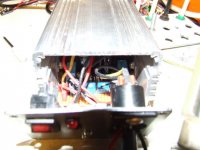
I finally got down to testing this PSU (please refer to the above schematic) after I managed to get a suitable casing.The case actually made it very easy for me to bolt the regulator ICs on either side providing ample cooling at the same time.
I've constructed the circuit exactly as given,but have added additional diodes-1N4002-between v adjust & output of each regulator IC
I've also added 200mA fuse to each secondary ac supply rail...which I'm not sure,if it's a good or a bad idea!??
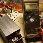
Q:There's a slight drift on both rails..but seem to almost lock on either 8.99 or 9.02 volts!! Why is this?
Any clever thoughts or suggestions?
Thanks!
I finally got down to testing this PSU (please refer to the above schematic) after I managed to get a suitable casing.The case actually made it very easy for me to bolt the regulator ICs on either side providing ample cooling at the same time.
I've constructed the circuit exactly as given,but have added additional diodes-1N4002-between v adjust & output of each regulator IC
I've also added 200mA fuse to each secondary ac supply rail...which I'm not sure,if it's a good or a bad idea!??
Q:There's a slight drift on both rails..but seem to almost lock on either 8.99 or 9.02 volts!! Why is this?
Any clever thoughts or suggestions?
Thanks!
Attachments
Last edited:
Thanks mjf.In case you've wondered,I'm using a 9-0-9v trafo instead.There's still unequal voltages ...since after an hour or so it does vary considerably for instance,+9.05,-9.10 or some other voltages no matter how much I adjust it!
Does not seem to settle to a fixed voltage! I did soak/run it for many hours to no avail.
C1b & C2b are 0.1uF/450v caps? I've followed the original circuit,bar for the 2 additional diodes across reg.o/p & voltage adjust trimmer!
I did change the elects caps ie:2x2200uf to better ones....didn't help much
Is it ok to have these fuses in the secondary? I've got 2x200mA slow ones.
The casing is actually from an old S.M.PSU for a 12v cigarette lighter.So don't think this should be a problem, Do you?
Last edited:
After many hours of tweaking,it's now showing some signs of improvement & has stabilized considerably! albeit for very slight fluctuations in the 2-5 mA region. I'd like to test it with some sort of resistive/capacitive load before I actually plug this into one of my projects,as I don't want to fry many hours of hard work work!
What value resistive/ capacitive load should I run this with?
Any suggestions? Thanks
What value resistive/ capacitive load should I run this with?
Any suggestions? Thanks
Last edited:
Taking lgreen's suggestion,I read through the data sheet for LM317, although the whole sheet refers only to LM117?.Anyway,here are few points I would like to clear up before connecting to a load.
Acc.to the data,the clamping diode between adj/o/p is only necessary if the cap is > 10uF & o/p voltage is > 25v! So would having one for a 10uf/9v result in malfunction?
It is clearly stated that,with no load the o/p voltage would rise,'cause the regulator(s) require an absolute min.of 10mA load current!
So,now I understand the reason for this rise in voltage on idle!
Here's a quick recap on the different/additional comp.I've used.
1.Additional Clamping diode between trimmer pot/IC adj. pin)
I.Trimmer pot=5k
2.C3a/C3b=10uF/25v
3.C5a/C5b=470uf/25v
4.C6a/C6b=0.1film cap
5.2x200mA Slow blow fuses on the ac secondary (These do have a resistance of 9ohm/fuse)
I have a 2 ch.digital Oscilloscope,which has a max.20 d.c range. however I'm not any good at using these generally.Can someone please give some guidance/advice on what to look for when measuring dc voltages.Yes, I've 2 probes too!
Last edited:
hello.
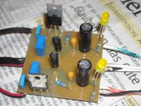
i often put some indikator lights at the output of the voltregs............a resistor with a standardled (red,yellow or green ) in series can show proper function or not.
with 9v output minus 2volt for the led and 10ma ledcurrent you get a res around 680ohm.......750ohm/0,5watt.
greetings
i often put some indikator lights at the output of the voltregs............a resistor with a standardled (red,yellow or green ) in series can show proper function or not.
with 9v output minus 2volt for the led and 10ma ledcurrent you get a res around 680ohm.......750ohm/0,5watt.
greetings
Thank you.Since there are already 2 holes drilled on the front plate for LEDs..I too was thinking if I should have these or not ..since,I thought that they also introduce some noise in to the circuit! If you think it is negligible,then I will definitely connect the LEDs.
Last edited:
Oh! I almost forgot to mention...I'm using LM 317T/337T reg.but not sure of the quality of these as these are 2 different,dubious brands bought on the E-Bay!
I've also connected a commercial type mains IEC Filter socket!(used the maxim
of throwing everything when one's in doubt!..seems to work all the time,,ha..ha)
Anyway,once I connected the LEDs,the voltage drift stopped considerably & didn't rise even with the the increase in temperature!.
So we can perhaps assume that the small loads presented by the LEDs actually help stabilizing the circuit as already mentioned in the DATA sheet.
I would like to hear from anyone else who has experienced this,The data sheet actually mentions about this with regard to no load conditions vs temperature.
I will try to plot the dc o/p on my scope & see how it performs.
The additional or alternate parts list would be;
Prim:220/230 Second;0-9-0-9 12VA Transformer.
Mains IEC Filter socket =1A
2x200mA slow-blow fuses (depending of course on the current drawn by the trafo!)
LM317T
LM337T
2x 5k 1/2w trimm pots
2x 1N4002 additional clamping diodes
2x tri-color LEDs with red /green retrained & other 2chopped off from the LEDs!
2x120ohm R
SWITCH CRAFT DC chassis plugs & sockets.
That's all folks!
Last edited:
Did you have any problems with dc voltage symmetry without the trim pots? What voltage are you running this at?
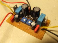
.......at the moment at +-18v,but i use this reg's with different applications too.so it is easier to get symmetry with trimpots for me (5k on the foto,but with lower output i would use 1......2k).the foto is without heatsinks..........and at the copperglad downside there are sometimes big foilcaps built in.
.......at the moment at +-18v,but i use this reg's with different applications too.so it is easier to get symmetry with trimpots for me (5k on the foto,but with lower output i would use 1......2k).the foto is without heatsinks..........and at the copperglad downside there are sometimes big foilcaps built in.
Last edited:
Oh! I almost forgot to mention...I'm using LM 317T/337T reg.but not sure of the quality of these as these are 2 different,dubious brands bought on the E-Bay!
........what is "dubious brand"? i have regs here from: national,fairchild,texas instr.,ons(motorola)............
I've also connected a commercial type mains IEC Filter socket!(used the maxim
of throwing everything when one's in doubt!..seems to work all the time,,ha..ha)
.....good idea - going the easy and save way.
greetings............
- Status
- This old topic is closed. If you want to reopen this topic, contact a moderator using the "Report Post" button.
- Home
- Amplifiers
- Power Supplies
- Small Power Regulated Power Supply