False alarm! They are indeed National & Signetics..I've confused them with 7008/9 reg.which I had used earlier! But I may have used one of each on my PSU!! could this be the problem below?
The PSU is not yet very stable,especially the + rail just keeps on drifting all the time.Just reading your reply prompts me to ask you,-I've used 5K trim pots,wouldn't it be better to use 2k trim pots instead since the trafo is only 9v?
There don't seem to be any dodgy connections either..could it be that one of the caps are leaking/shorting?
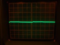
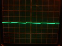
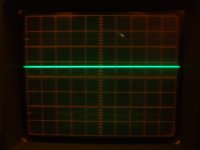
Did some tracing on the scope..& there's definitely something not right on the +9v rail!This confirms my doubts as some kind of oscillation or worse still something gone awry at the component level.The + supply is drifting 20-30 mv constantly!
I've no idea what's happening by looking at the trace!
Btw,the traces seem thick.because of the photographic angles!
Thanks!
Scope settings
Volts scale/cm= 0.5/cm
Time scale = 5msec/cm
=10msec/cm....?
Trace 1 +9v
Trace 2 +9v
Trace 3 -9v
I've no idea what's happening by looking at the trace!
Btw,the traces seem thick.because of the photographic angles!
Thanks!
Scope settings
Volts scale/cm= 0.5/cm
Time scale = 5msec/cm
=10msec/cm....?
Trace 1 +9v
Trace 2 +9v
Trace 3 -9v
Attachments
Last edited:
AndrewT,
Here are the voltages;
PIN 1adj 1
LM317 2 out LM337 2 in
3 in 3 out
At power on
+ Rail LM317T -Rail LM377T
Pin1 = 8.35 -7.81
Pin2 = 9.55 -13.78
Pin3 = 11.46 -9.08 fluctuating
After 30 min +
P1 +8.35 -7.83
p2 +9.55 -13.75
p3 +11.49 -9.08
Then on closer inspection of the copper side,I noticed a rather dodgy soldering on one place,re-soldered it...& now it appears to be rock steady! Left it running...will report back.
Strange,it was actually the + rail which was showing instability,yet all the readings on the - rail were unstable!I hope it's corrected now.
Thank you v.much!
Last edited:
317 (+ve reg) has 11.46V at supply. This is an average voltage. It also has ripple. The ripple could be +-10mVpk or it could be +-1Vpk. The highest -ve ripple must be subtracted from the average voltage (when the highest ripple occurs) This is Vin min.
The output voltage is 9.55V
You have Vin avg = 11.46V
The difference in to out is only 1.91V. subtract the worst case -ve ripple from the worst case supply voltage and the regulator cannot operate properly.
The -ve side regulator fares far better with Vin avg - Vout =4.67V.
But what happens to this differential when mains is at it's lowest and when current draw is at it's highest?
Your input voltages should be near the same. Find out why your input volatges are different.
Measure the ripple on the input for various output current conditions.
Check the datasheet for minimum differential voltage (drop out voltage).
Per Anders/mjf,
When you refer to ground,I presume you're referring to the '0' volt floating I hope!I don't remember exactly,but think the secondaries were putting out some 11+ volts.Yes, the r is quite low -120ohm/rail.The scope traces look thick 'cause I used a camera & it wasn't taken exactly horizontally & at fairly high intensity.
AndrewT
You make a very important point.I realize now the importance of o/p voltage/ripple subtract relationship! Very clearly explained too! It makes a lot of sense & very logical deduction too!
I'll measure the voltages again.
I have my doubts about the 2 larger filter caps..so will change them & see the results.
I've now left it on oh..for a good 4-5 hrs.Both voltages remain very steady,but NOT at the original settings! This has been the case all the time!
mjf's suggestion of using LEDs have actually helped in stabilizing the psu on power on,since the drift isn't as bad as earlier on no load conditions.
Thanks guys.
I found out that I had inadvertently soldered the - leg of the 2200uF cap on the + rail between reg.adj/res/trim.This was the cause of the instability! After correcting it,both rails are now working as they should & the strange step like spike display on the scope too is gone now!.
Then I extended the connection from the common-'0'- rail as shown in the circuit dia, to the psu chassis...& then suddenly both LEDs went off.A closer inspection showed that although both the fuses were intact,yet they were completely burnt out!
I,then disconnected the "ground", fitted new fuses..now they're working again.
Q:Has anyone any clue/explanation as to why this may have happened?
Reading from several articles,I find that some emphasize on the importance of this while others don't! It's all a bit confusing.
I think I was lucky,that I had 2 fuses on the secondaries,will,strongly recommend adding fuses to this circuit to anyone wishing build this psu! 'Though i accidentally shorted the rails a few times,the diodes & the fuses saved my day I am sure!
I thought I'd write a few notes on this PSU project since it was completed a few weeks ago & is now in regular use on my bench!
The most important thing are the two trimming pots! I managed to burn 2 of these since I wasn't careful enough when adjusting the voltages.In my haste to finish it quickly,I had inadvertently turned them far to quickly I suppose,which resulted in these burning out!
So turn them VERY VERY slow folks!
The tell tale signs are that no matter how much you adjust the trimpots,the voltages would fluctuate regardless & will show different levels on power up every time!
Secondly,incorporating fuses on the secondary side of the trafo actually prevented major disasters I think. I blew about 25 fuses mostly by accidentally shorting test probes,bad soldering on various projects,yet..no damage was done either to my circuits or to the psu itself!
Adding LED's,as voltage indicators help the PSU from voltage drift on no load conditions I think.(Perhaps some expert out there would know why I'm sure)
It's VERY quiet & I cannot hear any additional noise at all (This could also be possible/plausible that man is going deaf!)
Thanks for everyone who have helped & guided me through this.Much appreciated.
Thanks!
- Status
- This old topic is closed. If you want to reopen this topic, contact a moderator using the "Report Post" button.
- Home
- Amplifiers
- Power Supplies
- Small Power Regulated Power Supply