Hello again,
so I have just finished building it, I used circuit from datasheet, values are not the same, but close enough I think.
It works great, I have only tested it on 234Vac [measured it]
The way I have resistor network set to set output voltage, I get 387Vdc.
I did a bit more quick testing and this is what I got:
Vin: 233.5Vac
Iin: 2.046Aac
Vout:387Vdc
Iout:1.178Adc
Eff: 456w/477.74w = 95.5% [Good? I think it is]
And this voltage holds up as far as 760 measured watts on output. I didn't go for more because several reasons, like rectifier diods for input is probably only 4A, and for output I used two Mur4100, coz I couldn't get mur460's. This heat up pretty fast at max power tested, say within 10-15s you can't hold them[I guess about 55C].
For current sense I have 0.22R resistor and I get peak drop on it 1.9V @ 760w.
Now here is what I don't really understang, this voltage is on PIN4 of IC[didn't check this yet, I looked on resistor directly]. But as I understood (or not) that voltage on that pin should be max 1.5V. So can you all explain what is going on here, or what does that text in PDF mean , since I get more then I should [again I will have to check this right on PIN4 of IC]
So Steve[I just found yours, with 33262 ], this is right up your ally, also anybody else, please explain if you can
Edit: So only "big" diffrence I have from datasheet is, I have 1.2M and 12k resistor network to "see" input, and it should be 1.3M and 12k if you look at last schematic, 450w version
so I have just finished building it, I used circuit from datasheet, values are not the same, but close enough I think.
It works great, I have only tested it on 234Vac [measured it]
The way I have resistor network set to set output voltage, I get 387Vdc.
I did a bit more quick testing and this is what I got:
Vin: 233.5Vac
Iin: 2.046Aac
Vout:387Vdc
Iout:1.178Adc
Eff: 456w/477.74w = 95.5% [Good? I think it is]
And this voltage holds up as far as 760 measured watts on output. I didn't go for more because several reasons, like rectifier diods for input is probably only 4A, and for output I used two Mur4100, coz I couldn't get mur460's. This heat up pretty fast at max power tested, say within 10-15s you can't hold them[I guess about 55C].
For current sense I have 0.22R resistor and I get peak drop on it 1.9V @ 760w.
Now here is what I don't really understang, this voltage is on PIN4 of IC[didn't check this yet, I looked on resistor directly]. But as I understood (or not) that voltage on that pin should be max 1.5V. So can you all explain what is going on here, or what does that text in PDF mean
, since I get more then I should [again I will have to check this right on PIN4 of IC]So Steve[I just found yours, with 33262
], this is right up your ally, also anybody else, please explain if you canEdit: So only "big" diffrence I have from datasheet is, I have 1.2M and 12k resistor network to "see" input, and it should be 1.3M and 12k if you look at last schematic, 450w version
On the Datasheet I'm looking at (From ON semi) It says that the absolute max voltage on pins 1,3,and 4 is -1.0V to +10V.
Lower down it states that the current comparator range is 1.3-1.9V,with a note that it is measured with Vfb=0 and Vpin3=3.0V
They use 0.1ohms on the smaller designs,and 0.05ohms on the larger 450W design.
Swap out your 0.22ohm resistor for something smaller.
Lower down it states that the current comparator range is 1.3-1.9V,with a note that it is measured with Vfb=0 and Vpin3=3.0V
They use 0.1ohms on the smaller designs,and 0.05ohms on the larger 450W design.
Swap out your 0.22ohm resistor for something smaller.
but how is peak limited if it is not, not in a way if I load more and more the pfc. Yes, current does track input voltage, but I can't say it is limited fully, it is limited so that average looks like voltage waveform...maybe this is it, but it sure is not fully limites, as I could make short or way overloaded and something would go to hell
When drop on current sense resistor reaches some value, the current sense comparator switches off the mosfet, isn't it cycle-by-cycle peak current limitation? The inductor current swings between temporary peak and zero.
The peak current limit is a function of input and output voltage of course, so there may be no long-term peak current limit.
Since the peak current is limited further, the result must be higher duty cycle (for the same on-time) and therefore higher switching frequency.
That's my understanding of critical conduction mode PFC, however datasheet says:
I may be wrong on some things here, maybe others could exlain more. Markus? Eva?
The peak current limit is a function of input and output voltage of course, so there may be no long-term peak current limit.
Since the peak current is limited further, the result must be higher duty cycle (for the same on-time) and therefore higher switching frequency.
That's my understanding of critical conduction mode PFC, however datasheet says:
Which is unclear to me, because it would indicate, that peak current never exceeds 1.4V/Rsense.Set the current sense threshold VCS to 1.0 V for universal input (85 Vac to 265 Vac) operation and to 0.5 V for fixed input (92 Vac to 138 Vac, or 184 Vac to 276 Vac) operation. Note that VCS must be <1.4 V.
I may be wrong on some things here, maybe others could exlain more. Markus? Eva?
Same here, but:darkfenriz said:Which is unclear to me, because it would indicate, that peak current never exceeds 1.4V/Rsense.
I may be wrong on some things here, maybe others could exlain more. Markus? Eva? [/B]
That means to me, that only if sense is lost [don't see how that would happen, unless FB network would die on me[again, don't see how]] OR extremely high line [I would guess 268Vac][also don't see this happening], but by then I wouldn't care about this PFCAbnormal operating conditions occur during preconverter
startup at extremely high line or if output voltage sensing is
lost. Under these conditions, the Multiplier output and Current
Sense threshold will be internally clamped to 1.5 V.
Therefore, the maximum peak switch current is limited to:
Ipk(max) =1.5 V/R7
So I guess, current is not limited in sense of short circuit[well maybe if short, but not in 150% overload]. But its all good, I just don't know what is upper limit for it, since I am about 800w limited by input rectifier, only 2 diods in boost section, and then fet would come into play[but I can have 2 of them
]Core is only unknow at this point, when would it had enough.
Its 2.2cm^2 cross section, and my input will not be below 230v, so I guess this PFC will go in front of my smps, to power ClassD amps. Should be all way too much power for one small room
Update
While testing my smps, that I will use to power amps, I used PFC in front of smps. The way it was set, it was current limiting at 800w @ 362Vdc (instead of 388Vdc) with 0.22R resistor for current sense.
This was reason I couldn't get more then 770w @ 163Vdc from smps (+/-96V idle= 110w)
So I added another 0.22R as planed before, now I have no problem getting 1150w out of PFC, 387.7Vdc on 130R dummy load, this should be enough
Luka-
Pulled my original MC33262 PFC off the shelf last night and found out why it belw a 10A input fuse- I had the MUR 8100 output diode put in backward, creating a mess. Will correct that soon and retry it in near future. I expect much better results. Will still have to go with 250V output caps, for some safety headroom.
Steve
Pulled my original MC33262 PFC off the shelf last night and found out why it belw a 10A input fuse- I had the MUR 8100 output diode put in backward, creating a mess.
Will correct that soon and retry it in near future. I expect much better results. Will still have to go with 250V output caps, for some safety headroom.Steve
I used 2x mur4100 and they can't take the power, they are good for few seconds, but get hoooooot -> high power sucks, if you can't get some good elements, I hope I will be able to get 4x mur460 instead, I would like to stay free air cooled...
maybe there are some better diodes I could use? or just more of them?
-> high power sucks, if you can't get some good elements, I hope I will be able to get 4x mur460 instead, I would like to stay free air cooled...maybe there are some better diodes I could use? or just more of them?
If you can get them, I would recommend either MUR880 or MUR8100 for both your mains rectifiers and the catch diode. I read in some obscure Motorola App note a while back (before they spun-off ONSemi), that, since high-frequency pulses were being drawn through the main rectifiers, they should be ultra-fast types. There is some difference of opinion there, but I would prefer to err on the side of caution.
No need for high speed rectifiers there. The current only reverses at 60Hz. The fact that the load current is rippling at a high frequency (not even by much since the inductor resists change in current) is irrelevant.If you can get them, I would recommend either MUR880 or MUR8100 for both your mains rectifiers and the catch diode. I read in some obscure Motorola App note a while back (before they spun-off ONSemi), that, since high-frequency pulses were being drawn through the main rectifiers, they should be ultra-fast types. There is some difference of opinion there, but I would prefer to err on the side of caution.
I'm trying to get this PFC chip to work in the circuit I am using.
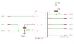
I built my circuit just like the circuit in the datasheet of the mc34262 for the 450W (400V @ 1.125A) supply. For some reason I cannot get this part to work properly, the MOSFET never switches causing the output to be the rectified input. The only difference I can tell from the conditions described here and what I am using is that I have a 120V AC supply (USA), not 240V, and I am using a 0.05 ohm current sense resistor instead of 0.22 like used here. The picture is my circuit schematic in EAGLE; one is the high voltage stuff and the other is the surface mount mc34262.
Is there anything I can try/change/test to get this working or at least figure out why it is not working?
Thanks in advance,
Brian
Attachments
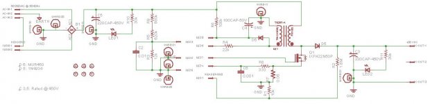
I would say your startup resistor could be too high value, does IC ever get 10v or how much it needs to start? I used pretty big one, and is takes about 3-4s before it starts, that's how much time is needed to fill supply C for ic to some 10v or so volts. But as I see, problem is that 220uF cap on input, instead of 2uF
And you have wrong input capacitor, 220u
It has to be 2uF!
you don't take DC with pfc, but rectified AC as input
That's why those 600k+ resistors are there, to sense where at any time AC value is on input
Remove that 220u and replace it with good 2uF/400v cap, non polarized, poly or what ever is good here
If you check schematic again, good, you will see that C5 HAS value, and it is 2, on the left side of the symbol
Last edited:
you have wrong input capacitor, 220u
It has to be 2uF!
Wow, I didn't even realize that cap had a value, must've overlooked that.
The description of how eveything works in the datasheet makes much more sense now; I was wondering how the other side of the inductor would get any current without an AC signal.
I looked at a few of the pins on the chip yesterday and pin 7, the gate driver, would turn on at the very start, but not enough voltage to switch the mosfet, only about 4V or so, and only lasted for about 3 or 4 cycles. I decided to make sure the circuit was getting power so I tanned in on pin 8, Vcc, would charge to about 12V~13V then discharge to about 8V (Vcc < ~8V turns off the chip and Vcc > ~12V turns the chip back on once off). Seemed like it would charge the cap, but once the chip required any amount of current the cap would discharge until the chip would turn off and not require current anymore, then start the process back over again.
Also, I don't have an RFI filter on the input, just a 6ft power cable for "inductors." Will this cause the chip to malfunction, not work, or change how the circuit works? Or is this just to prevent the higher frequency pulses from the switching MOSFET from entering the grid?
The current sense resistor, will changing that value change the current available on the output?
Thank you very much,
Brian
you can make the system open loop by wrapping the comp pin directly into the -feedback pin through a 50K resistor and make a -x gain opamp.
this is what i did to parallel 4 of them. yep, they interleave in an ad-hoc manner, and i made a 4 phase TM mode PFC, so far i've made 2 phase and 4 phase prototypes.
anyhow, you can use a RC network to provide constant on or off time, or you can use an RC network to provide traditional operation (just run the pfc chip from a separate power supply) --read the L6562 datasheet!
power flow is limited by the 1.x volt limit on the current sense resistor.
you won't be able to push more current through the inductor until the output of the system drops below 1.4 times the ac input, and then the inductor saturates.
- Status
- This old topic is closed. If you want to reopen this topic, contact a moderator using the "Report Post" button.
- Home
- Amplifiers
- Power Supplies
- Power Factor Correction - PFC with MC34262