I am building a Sigma11 from AMB Labs, C5 is specified as 1 x 2700uF at 63V or 2x1500uF at 63V ... is it a big deal to do two 2200uF at 50V? I am not worried about voltage on the caps because I am configuring it for 5V DC but is the extra capacitance a big deal, I am inclined to say no... but I am not sure of the background EE theory in PS design...
I don't know what a Sigma11 is, but it will probably work. But why do you what to use two 2200uF caps when one will do?
An EE might tell you that in some cases the ESR of the output cap can effect stability. In fact, an ESR of 0 may cause a regulated supply to become unstable.
An EE might tell you that in some cases the ESR of the output cap can effect stability. In fact, an ESR of 0 may cause a regulated supply to become unstable.
HaLo6 said:2x1500uF at 63V ... is it a big deal to do two 2200uF at 50V? I am not worried about voltage on the caps because I am configuring it for 5V DC but is the extra capacitance a big deal, I am inclined to say no... but I am not sure of the background EE theory in PS design...
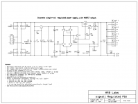
It helps to post schematics and any other helpful links so we dont have to assume and/or hunt. Which I didn't bother
3000 to 4400 uF is about an increase of 50% not in excess when considering initial tolerances plus aging of these bulk caps.
I would question such a drastic change in DC voltage from 50- 60V to 5V tho? I think with this kind of change there is whole lot more to consider. Is this a linear or SMPS
")
AndrewT said:6Vac might be a bit too low for a regulated output of 5Vdc
Try to find 7Vac to 9Vac for this output voltage.
I think he is using 12Vac and 50V caps if I read his intent correctly
Hi
Since you have chosen to build a high performance regulator circuit, rather than a generic 3-terminal one. You also might want to consider not using a toroid transformer but instead an EI one with a split bobbin ie pri-secondary wound side by side.
Common mode noise is any noise signal that is common to both the active (hot) and neutral mains leads. This is not coupled through the transformer magnetically, but capacitively. The higher the capacitance between primary and secondary windings, the more common mode noise will get through to the amplifier. The much loved toroidal transformer is much worse than conventional "EI" (Ee-Eye) lamination transformers in this respect because of the large inter-winding capacitance. An electrostatic shield will help, but these are uncommon in mass produced toroidal transformers. The conventional transformer is usually better, and by using side-by-side windings instead of the more common (and cheaper) concentric windings, common mode noise can be reduced by an order of magnitude.
Input mains filters can remove either form of high frequency noise component to some degree, and large spikes can be removed using Metal Oxide Varistors (MOVs) that effectively short circuit the noise pulse, reducing it to a level that is (hopefully) inaudible. Contrary to the beliefs of some, there is no panacea for noise, and it is best attacked in the (offending) equipment, rather than the now popular (but mainly misconceived) notion that an expensive mains lead will cure all.
from a good link for Power Supply Design/Audio stuff http://sound.westhost.com/power-supplies.htm#supply-requirements
AndrewT said:The worst case voltage from 9Vac is ~ 9 * 1.414 * 1.3 * 1.06 -1 ~=16.5Vpk
Is that basically the trafo rating x RMS factor x safety margin x effeciency? So all the caps on the board could essentially be based on the this formula?
So I am a little confused on "center tap" How does that effect the total voltage as compared to dual or single secondaries? is 9VCT like dual 4.5V secondaries? So I would need ~15VCT to get around 7.5V secondaries to get the 5VDC out of the PSU? or am I on another planet...
AndrewT said:6Vac might be a bit too low for a regulated output of 5Vdc
Try to find 7Vac to 9Vac for this output voltage.
You can just about use 16Vdc caps for the smoothing at these low voltages.
The worst case voltage from 9Vac is ~ 9 * 1.414 * 1.3 * 1.06 -1 ~=16.5Vpk
No safety margin in there.HaLo6 said:
Is that basically the trafo rating x RMS factor x safety margin x effeciency? So all the caps on the board could essentially be based on the this formula?
1.414 converts the sinewave to peak value.
1.3 is a guess at the worst case regulation for a very low VA transformer. The factor is 1 + [regulation/100], 30% gives 1.3, 12% gives 1.12
1.06 is the maximum tolerance for the 240Vac supply in the UK, i.e. 254Vac.
I am only using a 2x6VAC trafo.
as I said 6Vac is a bit low for worst case conditions. 12Vac, if you series connect the two secondaries, will give very high dissipation in the regulator. Max Vdc from 12Vac 30% regulation is ~22Vdc and that requires 17Volts to be absorbed by the regulator to give an output voltage of 5Vdc. Note the regulator dissipation ~doubles by changing the transformer from 9Vac to 12Vac.
HaLo6 said:Awesome thanks a lot I will add a set of those to my Mouser order! So if these are close to the same price as the toroids , why don't more people use these?
In my experience the EI's should be cheaper. The toroids have better regulation typically at the same rated current. But using Vregulators at lower currents this should not even be a concern. Toroids have lower profile, less stray fields so allows more compact packaging, Also toroids look a little more high tech/cool. EI's have more leakage ind. and less interwinding cap. which is favourable for powerline noise isolation. Everything in engineering comes down to a set of tradeoffs. You just have know your priorities and pick your poison.
- Status
- This old topic is closed. If you want to reopen this topic, contact a moderator using the "Report Post" button.
- Home
- Amplifiers
- Power Supplies
- Too much capacitance?