http://sound.westhost.com/project39.htm
Some questions:
Digi-key doesn't have the BC558 in stock. What's a suitable replacement?
Can I replace the aux transformer and rectifying diodes with a DC wall-wart supply? How does the earthing work?
I don't know anything about relays. What should I use?
Some questions:
Digi-key doesn't have the BC558 in stock. What's a suitable replacement?
Can I replace the aux transformer and rectifying diodes with a DC wall-wart supply? How does the earthing work?
I don't know anything about relays. What should I use?
Do I need to earth the case if I use a wall wart?
If I can use any old PNP transistor, is the 0.65V switching determined by the circuit around it, then?
Do all relays have the same pin-out? What type of current and voltage ratings are important? Coil current, coil voltage, contact rating, control off/on voltage? Ugh.
If I can use any old PNP transistor, is the 0.65V switching determined by the circuit around it, then?
Do all relays have the same pin-out? What type of current and voltage ratings are important? Coil current, coil voltage, contact rating, control off/on voltage? Ugh.
Will this work for the PNP transistor?When a voltage of 0.65V is sensed across the relay, Q1 turns on, and instantly completes the charging of C2
http://search.digikey.com/scripts/DkSearch/dksus.dll?Detail&name=BC327GOS-ND
Will this work for the relay, or is it overkill?
http://search.digikey.com/scripts/DkSearch/dksus.dll?Detail&name=255-2387-ND
This one's rated higher, but is cheaper for some reason.
http://search.digikey.com/scripts/DkSearch/dksus.dll?Detail&name=Z215-ND
Yes, because there is mains voltage present in the case at the relay contact.454Casull said:Do I need to earth the case if I use a wall wart?
All silicon transistors switch at that voltage level. You can also use new PNP transistors, they need not be old.454Casull said:If I can use any old PNP transistor, is the 0.65V switching determined by the circuit around it, then?
")
No.454Casull said:Do all relays have the same pin-out?
The coil voltage should be the same as the supply voltage. If it is smaller, you will have to use a series resistor. Then you will need the coil current or resistance to determine the resistor value. The lower the coil current, the better, because you want to waste as little energy as possible.454Casull said:What type of current and voltage ratings are important? Coil current, coil voltage, contact rating, control off/on voltage? Ugh.
Contact rating is important. Voltage rating should be AC and greater than or equal to the mains voltage. Current rating should be greater than or equal to the current you are switching and should be given for inductive load. The current depends on the transformer you use, but Mr. Elliott's recommendation to use 10 A or higher will be okay for the vast majority of audio amplifiers.
All other values should be of no concern for this application.
Yes. Direct replacements for the BC558 are BC556/BC557/BC559/BC560. They are all the same, except that some of them have higher voltage ratings than the BC558.454Casull said:
Will this work for the PNP transistor?
http://search.digikey.com/scripts/DkSearch/dksus.dll?Detail&name=BC327GOS-ND
Both will work. The Omron relay will hold ~double as long, but both will probably live longer than the entire rest of the amplifier, as long as there is no short at the relay output.454Casull said:Will this work for the relay, or is it overkill?
http://search.digikey.com/scripts/DkSearch/dksus.dll?Detail&name=255-2387-ND
This one's rated higher, but is cheaper for some reason.
http://search.digikey.com/scripts/DkSearch/dksus.dll?Detail&name=Z215-ND
Does the polarity/direction of current through the relay coil matter?
Also, I'm still not sure about what the earth symbols mean here: http://sound.westhost.com/p39-fig2.gif. If one takes mains into the chassis, then I could see needing to earth it and then you have your earth, but if I use a wall-wart I won't have that.
Also, I'm still not sure about what the earth symbols mean here: http://sound.westhost.com/p39-fig2.gif. If one takes mains into the chassis, then I could see needing to earth it and then you have your earth, but if I use a wall-wart I won't have that.
Usually not. Only, when you have a relay with built-in flyback diodes or LEDs454Casull said:Does the polarity/direction of current through the relay coil matter?
That will be the common ground then.454Casull said:Also, I'm still not sure about what the earth symbols mean here: http://sound.westhost.com/p39-fig2.gif. If one takes mains into the chassis, then I could see needing to earth it and then you have your earth, but if I use a wall-wart I won't have that.
I built the ESP soft start on an earlier project and it works fine. It is a bit complex and the need (or preference) for a auxiliary supply to run it is a downer.
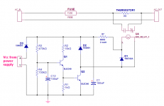
Below is something simpler - it runs off the main power supply and uses a thermistor as the inrush current limiter (safer than the power resistors). There is a 1 second delay before the relay closes, bypassing the thermistor.
Below is something simpler - it runs off the main power supply and uses a thermistor as the inrush current limiter (safer than the power resistors). There is a 1 second delay before the relay closes, bypassing the thermistor.
Attachments
theAnonymous1 said:Can't a simple 555 timer circuit be used instead?
Simpler than the RC I've shown in post #10?

MJL21193 said:Simpler than the RC I've shown in post #10?
Parts count wize, yes. Your circuit has 11 parts (minus the relay and relay diode); a 555 circuit needs only 3.
I built the circuit from here a few days ago to take an amplifer out of mute state after power on. It draws about 32mA @ 12V with the relay shown. Use a bigger relay and some large power resistors and you have a soft start.
An externally hosted image should be here but it was not working when we last tested it.
A soft-start time of 1 s is much too long. The transformer and the connected circuit(s) remain in an unstable undervoltage state far too long. The soft-start time should be something like 3 cycles, i. e. 0,06 s for 50 Hz.Originally posted by MJL21193
There is a 1 second delay before the relay closes,
The relay does not improve the efficiency. On the contrary the relay consumes power, while it is activated.Originally posted by star882
The easiest way is to use just a NTC inrush limiter. If more efficiency is desired, parallel it with a relay connected to the output of the supply. The relay will bypass it once the precharge is complete.
The NTC will remain hot during operation. Therefore it could not serve its function, if only a short voltage interruption ocurred. The purpose of the relay is to take the current off the NTC, so that it can cool down and serve its function at any time.
pacificblue said:
A soft-start time of 1 s is much too long. The transformer and the connected circuit(s) remain in an unstable undervoltage state far too long. The soft-start time should be something like 3 cycles, i. e. 0,06 s for 50 Hz.
Seriously, did anyone bother to look at the schematic in post #10 that I'm refering too? It uses a thermistor, not power resistors.

MJL21193 said:Seriously, did anyone bother to look at the schematic in post #10 that I'm refering too? It uses a thermistor, not power resistors.

In a high power circuit, the resistive losses in the NTC will be greater than the power used by the relay.pacificblue said:
A soft-start time of 1 s is much too long. The transformer and the connected circuit(s) remain in an unstable undervoltage state far too long. The soft-start time should be something like 3 cycles, i. e. 0,06 s for 50 Hz.
The relay does not improve the efficiency. On the contrary the relay consumes power, while it is activated.
The NTC will remain hot during operation. Therefore it could not serve its function, if only a short voltage interruption ocurred. The purpose of the relay is to take the current off the NTC, so that it can cool down and serve its function at any time.
- Status
- This old topic is closed. If you want to reopen this topic, contact a moderator using the "Report Post" button.
- Home
- Amplifiers
- Power Supplies
- ESP soft start circuit