Hello all,
I am looking at the possibility of the following, and wanted the opinions of those with more knowledge here.
I've been thinking about designing a variable voltage Buck SMPS. (Basically, I'd like something to take a 15V DC input down to, say 5-12V with 1 or 2A max output current. I know, in general, this would be better served probably with a linear regulator, but I want a project to learn the basics where I don't have to worry so much about high voltage/high current. I could also use a basic small bench supply for some of my other electronics experiments, so it would actually serve a purpose once finished.
What I was thinking of would be a simple buck converter, where the PWM signal is generated from a microcontoller (Either one of Microchip's or Atmel's chips which has pwm. In the past, I've done the interfacing between microcontroller and display / etc. for user i/o, so I'd just have to figure out the sense and the PWM output. I don't see it as too big of a deal.
Now, for my questions, which I haven't been able to find much information on:
1) Is it feasible to create a buck converter which can handle a varying output voltage like that?
2) Assuming that it is, is it worth the additional work to implement a synchronous buck converter, or just deal with the slightly lower efficiency of the regular one?
Joral
Hi, and welcome to the world of switch-mode nightmares.
I have never done these myself, but since there are plenty of buck-based laboratory power supplies - well, you know it after you've tried it! Frequency compensation should be designed carefully.
IMHO using synchronization is recommended for self-educating purposes. It is obviously more difficult but well worth experimenting. Especially if you some day find yourself working with these issues. You can never know too much and practical experiments Do teach a lot! Then again, you can still achieve good enough efficiency with diode rectification at these power levels. Depending on the frequency.
Joral said:
Now, for my questions, which I haven't been able to find much information on:
1) Is it feasible to create a buck converter which can handle a varying output voltage like that?
I have never done these myself, but since there are plenty of buck-based laboratory power supplies - well, you know it after you've tried it! Frequency compensation should be designed carefully.
Joral said:
2) Assuming that it is, is it worth the additional work to implement a synchronous buck converter, or just deal with the slightly lower efficiency of the regular one?
Joral
IMHO using synchronization is recommended for self-educating purposes. It is obviously more difficult but well worth experimenting. Especially if you some day find yourself working with these issues. You can never know too much and practical experiments Do teach a lot! Then again, you can still achieve good enough efficiency with diode rectification at these power levels. Depending on the frequency.
You should have no problem using a PIC to control a buck converter. I recently completed my dissertation which used a PIC18F1330 to control a small boost DC/DC converter successfully. I would highly recommend this device as it includes all the PWM/ADC features you will need. The PWM duty ratio can be controlled easily in software, allowing you to vary the output voltage. By feeding the output voltage to one of the ADC inputs via a voltage divider you can create a regulated supply.
I have attached the circuit diagram for my project. Even though it is for a boost converter, may provide you with some useful information
I have attached the circuit diagram for my project. Even though it is for a boost converter, may provide you with some useful information
Attachments
Buck Converters
Hi,
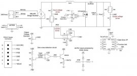
I would not recommend to make the regulation part of the Buck converter in SW... I think it would be better for you to use a syncron buck contoller like the TI TPS40021 (5V input) or the TPS40195 for 12V or mayby one that you can get in your neighbourhood.
Anyway, I would set up the converter to generate the minimum needed output voltage by default, and then manipulate the DC feedback by adding extra resistor(s) as you increase the voltage. This way you can "programme" the min/max output voltage in HW and let the µC choose what the output voltage should be.
(Sorry for the poor picture Q)
I hope this helps you
Best regards
Jens
Hi,
I would not recommend to make the regulation part of the Buck converter in SW... I think it would be better for you to use a syncron buck contoller like the TI TPS40021 (5V input) or the TPS40195 for 12V or mayby one that you can get in your neighbourhood.
Anyway, I would set up the converter to generate the minimum needed output voltage by default, and then manipulate the DC feedback by adding extra resistor(s) as you increase the voltage. This way you can "programme" the min/max output voltage in HW and let the µC choose what the output voltage should be.
(Sorry for the poor picture Q)
I hope this helps you
Best regards
Jens
Attachments
Joral said:Jens,
Is there a particular reason you would argue against a software implementation?
Well it depends on the platform, you can get dedicated digital buck controllers, that work well, but to build one from scratch, will take a great deal of time....IMO
If you build it yourself, you will need a SW compensation network (digital version of type II or III) This can take some time to build + you will need to work out the right parameters in the DSP.
If you want to learn how the buck DC/DC converter works, I think it is better to start analog, as it is a bit of work just understanding the basics. The you can go digital in the next generation.
\\\Jens
Joral,
I would like to second Jens' option to try and build a regulator using a "linear" controller instead of a uC... It will give you better understanding of the analogue control loops and other parameters that are in play when building a SMPS. The digital should be a step afterwards, applying your "analogue" knowledge in the digital world.
Even better, we normally teach graduates and trainees in our lab to build a converter using only opamps and comparators. We let them build a self-oscillating ramp generator, (5 resistors, 1 capacitor and 1 comparator), drive comparator, current control loop (the tricky bit) and a voltage loop wrapped around the current loop. (i.e. a conductance-controlled voltage regulator).
This way, we teach our students all the basics they need to know about SMPS, because they usually run into all the various "problems" associated with SMPS design, and especially SMPS control theory.
Good luck!
B
What about a TL494? Texas Instruments even has a pdf released on building a buck converter with one.
Look at page 25 in the PDF:
http://focus.ti.com/lit/an/slva001d/slva001d.pdf
You just drive a Transistor or MOSFET with the TL494, and take the feedback from a voltage divider on the output. Use a POT to vary the voltage.
I'm planning on building a variation myself of this TL 494 circuit to charge a 3.7V Li-Ion from 12V using PWM.
The Simplest Buck regulator would be using one of the simple switchers. It consists of a Switching regulator in a TO-263 or TO-220 Package, a inductor and a external diode. You can build one in about 15 minutes.
http://www.national.com/mpf/LM/LM2576.html
If your going to be using the Output voltage for a digital circuit, I would recommend adding a Pi Filter to the switcher output to remove noise.
http://www.national.com/mpf/LM/LM2576.html
If your going to be using the Output voltage for a digital circuit, I would recommend adding a Pi Filter to the switcher output to remove noise.
- Status
- This old topic is closed. If you want to reopen this topic, contact a moderator using the "Report Post" button.
- Home
- Amplifiers
- Power Supplies
- Learning Project - Buck SMPS