Hi all, it seems I have broken my reflektor d mini. I got a 24v load into the wrong end of my DAC so it will have touched the output of the reflektor d and now the LEDs on the output of both of my reflektor d mini are not lit any more. Presumably I have blown a component, but can anyone guess as to which one is likely to be faulty or how to test them?
Thanks,
James
Check vgs and vbe on mosfets and bjts, rds for jfets. Few V for mosfets, sub V for bjts, few decades of ohm for jfets. Its probably the output mosfet or the jfet near it that has been compromised, but not necessarily so.
Sorry to hear that about your DAC chips. These regulators utilize the CCS as a current limit guard also and sometimes manage to escape the drama.Thanks for the help. Turns out when I pulled things apart for diagnosis, the reflektor regulators are just fine when not connected to the DAC, so that is good news. Both channels of my DAC chips are fried though, not so good news...
Thanks again,
James
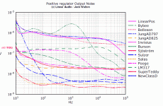
Have anyone measured the output noise in Vrms of the bib? what is the measured output noise?
I see the nv/SqHz I agree its bandwidth based calculation but did anyone measured it on the Vrms wise? Do you see a short noise band on CRO with 1mv per division setting?( As I have a CRO which can go till 1mv/div at best ).
I see the nv/SqHz I agree its bandwidth based calculation but did anyone measured it on the Vrms wise? Do you see a short noise band on CRO with 1mv per division setting?( As I have a CRO which can go till 1mv/div at best ).
Attachments
Can anyone reply on the noise measurement please?Have anyone measured the output noise in Vrms of the bib? what is the measured output noise?
I see the nv/SqHz I agree its bandwidth based calculation but did anyone measured it on the Vrms wise? Do you see a short noise band on CRO with 1mv per division setting?( As I have a CRO which can go till 1mv/div at best ).
Salas V1.2R info
Hello everybody and thanks to Salas for his magnificent work.
I'm going to build the Salas V1.2R PSU and I would like to know some info:
Is the led rated for 1.8V @ 20ma?
How much is the Idss for the 2SK170 and 2N5457?
Thanks in advance for any help.
Bruno
Hello everybody and thanks to Salas for his magnificent work.
I'm going to build the Salas V1.2R PSU and I would like to know some info:
Is the led rated for 1.8V @ 20ma?
How much is the Idss for the 2SK170 and 2N5457?
Thanks in advance for any help.
Bruno
Thank you Salas.
Is it possible to use any fet with 6-8ma and 3ma Idss?
Is there a way to check for oscillations in the circuit? I would Like to test the SSLV1.1 I built without any results (the behavior is erratic).
Thanks again
No their Vgs (off) range and noise characteristics are designed in.
To check for oscillations use a scope and probe the rail output. Choose AC input mode on the scope 5mV vertical and 50uS horizontal. Also use the short ground probe's tip coil like wire attachment.
The 1.1 is so widely and successfully used that's odd to be erratic. There's either a problem in the build or the application is not Kelvin 4Wire compatible. Convert it to 2Wire. See this link about it: http://www.diyaudio.com/forums/power-supplies/192625-sslv1-1-builds-fairy-tales-346.html#post4595171
Bipolar Salas V1.2R + Keantoken Multiplier and some measurements
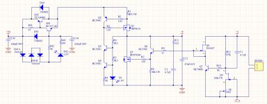
I made a version of V1.2R for +30Vdc and -30Vdc, coupled with Keantoken's Multiplier (K-Multiplier) for powering Aleph (X)Ono phono (clone) stage. Here's the circuit (only +30V shown):
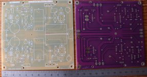
And the PCB:
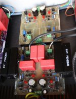
Here's the populated PCB:
The input of this regulator is fed with +40Vdc & -40Vdc, coming from a C-R-C full-bridge rectifier.
I measured the peak-to-peak ripple at the input of this shunt regulator (+40V only):
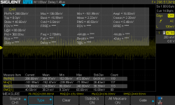
And at the load (+30V only):
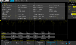
Measurement at the load was performed with the aligator clip (for ground) and the probe tip (for +), since I'm using the 4 wire Kelvin connection (the + and GND terminal is separated a bit long, about 4 cm), so I think I picked up some additional noise there.
Measurement at the input was performed with the oscilloscope's ground spring.
Comments and suggestions are welcome.
I made a version of V1.2R for +30Vdc and -30Vdc, coupled with Keantoken's Multiplier (K-Multiplier) for powering Aleph (X)Ono phono (clone) stage. Here's the circuit (only +30V shown):

And the PCB:

Here's the populated PCB:

The input of this regulator is fed with +40Vdc & -40Vdc, coming from a C-R-C full-bridge rectifier.
I measured the peak-to-peak ripple at the input of this shunt regulator (+40V only):

And at the load (+30V only):

Measurement at the load was performed with the aligator clip (for ground) and the probe tip (for +), since I'm using the 4 wire Kelvin connection (the + and GND terminal is separated a bit long, about 4 cm), so I think I picked up some additional noise there.
Measurement at the input was performed with the oscilloscope's ground spring.
Comments and suggestions are welcome.
Scoping at the output should show a flat line. Maybe thickened by random noise but no ac patterns. Try two wire output mode too by linking F+ with S+ locally at the output connectors. You already have no separate F0s, but a star? That's not in the design. Maybe its half sensing over a wide loop area now and picks much noise (if it is not oscillating).
Hello Salas,
I measured again the 30V+ ripple. This time I set the oscilloscope in "normal mode" (before, I used: detect-peak mode) with 1X attenuation probe. I set the horizontal scale at 50us/div. I could see it is indeed a random noise. But the peak-to-peak amplitude is about 12mV. This is too high, right?
I tried using 2 wire method (connecting Force and Sense directly together at the regulator output), but still the same. So is it oscillating??
About the PCB ground star, I merely copy the Bipolar design for V1.2 shown in the post#1898. But anyway, I added K-Multiplier before the SSLV....
I'm trying to debug my regulator. Perhaps, first thing I do is to test only the V+ section (while disactivating the V- section) to see if the use of common F0 is the root cause? The load is aleph Ono (current consumption is about 110mA for the V+).
If it does not have a distinct AC pattern riding on the line it isn't oscillating. 12mV thick line is too thick for random noise unless it is not coming out of the build but its picked common mode from the environment. Needs short return on the probe as you know. The "coil" pointy thingy. One good comparative clue is to power it off as it is probed and see if the random noise on the screen remains the same or not.
In #1894 for V1.2, I noticed that you take the regulator output directly from Zobel network. I did not do this for V1.2R in my pcb layout. Dooooh 
Anyway, I searched in this thread about my problem, and found out that RCruz had 30mV ripple, and played a bit with the value of R & C for the zobel. Also noted that someone here recommended putting elco right at the output (ie between Force and Gnd).
I tried installing a 22uF elco right at the output F+ and Gnd, and the ripple went down to just about 4mV peak-to-peak. Can I further improve this by taking the voltage output directly from the zobel network (i.e. I have to change the position of the zobel network R13 and C3 in V1.2R, so that it is closer to the regulator output)?
Hello Salas,
After debugging my circut, I found out that the K-Multiplier does not work. It is actually adding noise, and one time I could see that at the output of the K-Multiplier (in this case is also the input of SSLV v1.2R), there was some noise riding on a 100Hz square waves. Dooooh So, I guess my K-Multiplier was oscillating.
I replace the K-Multiplier by just a small elco, and I'm down to 2mV pk-pk at the output of SSLV. Now, I'm happy! Guess I could put a C-R-C in front the SSLV to improve things a little bit. Thx for support, Salas! You're the best!
After debugging my circut, I found out that the K-Multiplier does not work. It is actually adding noise, and one time I could see that at the output of the K-Multiplier (in this case is also the input of SSLV v1.2R), there was some noise riding on a 100Hz square waves. Dooooh
 So, I guess my K-Multiplier was oscillating.
I replace the K-Multiplier by just a small elco, and I'm down to 2mV pk-pk at the output of SSLV. Now, I'm happy! Guess I could put a C-R-C in front the SSLV to improve things a little bit. Thx for support, Salas! You're the best!

- Status
- This old topic is closed. If you want to reopen this topic, contact a moderator using the "Report Post" button.
- Home
- Amplifiers
- Power Supplies
- The simplistic Salas low voltage shunt regulator
