Slowly disappears from the scope screen,,,,,
So the nasties are not from the shunt but being picked up from the environment.
Anyway, I just tamed the simulator.
It all depends on the termination zobel.
Too much resistance and the thick line appears.
Too low capacitance... the same...
Too high capacitance and the results are even worse.
What I need now is a good way to determine the exact values for the zobel, minimizing the cap value.
Below 15uF, with any resistance in the zobel, the thick line appears.
fixing to 15u I found that I can use 0.05ohms to get a perfect picture.
How can I determine the best zobel values ?
I am tackling this problem too now in time.
The sim does not work. It needs the following component in the library, for ".include RC-MODELS-2.txt"
Can you supply that?
thanks in advance albert
can we use BF256 instead of 2sk170 jfet? for the shunt regulator?
No
Hello. I have seen some builders using the SSLV1.1 for that phono. Its a dual adjustable.
SSLV1.1 builds & fairy tales
SSLV1.1 builds & fairy tales
The last ultimate version of Salas Shunt Regulator?
Hello Salas,
I've been following and reading this thread for 2 weeks and boy... it's a loooong thread. Could you kindly confirm if this version : V1.2R (in post #3200) is the last ultimate version of your shunt regulator?
I am going to build it soon, and I promise I will give a feedback
Hello Salas,
I've been following and reading this thread for 2 weeks and boy... it's a loooong thread. Could you kindly confirm if this version : V1.2R (in post #3200) is the last ultimate version of your shunt regulator?
I am going to build it soon, and I promise I will give a feedback
Hi,
I have two regulators V 1.0. I have 25 V in input and I want 15 on output with 100mA current. The positive regulator gives me a max voltage of 17 V, while the negative does not go higher than 13.5 V. I need 15 V, what can I tweak to get where I need ?
Thanks,
Davide
I have two regulators V 1.0. I have 25 V in input and I want 15 on output with 100mA current. The positive regulator gives me a max voltage of 17 V, while the negative does not go higher than 13.5 V. I need 15 V, what can I tweak to get where I need ?
Thanks,
Davide
Most possibly the IDSS of the JFET (the one nested in the BC5xx transistor) is less than its respective one in the positive polarity regulator. Choose higher value for the Vref resistor or trimmer, the one located in series with that JFET in the negative polarity regulator, to compensate.
Hi Salas
I'm trying to sort some things out between finishing some fixes on my DCB1 and starting a simplistic RIAA. One issue is related to a failed battery power supply on a head amp I'd like to replace and make usable. I inquired with Tea Bag about availability and whether the SSLV might solve my problem. He suggested asking more questions.
My question/description:
I have a failing battery power supply on a ZYX CPP-1 head amp that I picked up at a reasonable price years ago before I got into DIY. I'd like to be able to use it.
I started looking into replacing the batteries, but I was thinking that one of Salas' shunt regulated supplies would be just as good, if not better. I have tried using battery supplies with a couple of projects I've made, and they sound good, but they're a hassle to monitor and I've had them cut out and send horrendous noise through my system a few times.
The CPP-1 can operate from its internal Cadmium cells which are (9) 1.2V 1100mA or the 12V 1A wall wart it came with that is used to recharge the cells. I'd like to pull the cells out that won't hold a charge anymore and replace the power supply with an SSLV in its own external case. I'm assuming that the SSLV would be the right choice?
Tea's response:
The SSLV1.1 that is a lot of current to overcome, you may need to use a large heatsink. However I am not sure it really needs that much. You would have to check with someone else on that. So you might need as much as 1200ma dissapatch @12v. Also, I would need to supply the kit with IRF9530 for both CCS and Regulator portion. Doable, I just need to be reminded.
I actually have more than one project running on battery supplies that I'd like to have a quiet PSU alternative to including a mini DSP which can use 4.5 - 24V, and a BoozeHound phono RIAA which can use 12 - 24V power supplies.
Any guidance you could offer would be greatly appreciated.
Regards
Kevin
I don't know what circuit is in that ZYX pre-pre and if it can work equally well without a floating supply (batteries) but in any case its power consumption will not be a problem since the manufacturer states only 0.8W for it. ZYX Official Website - CPP-1 v2 Pre-pre Amplifier
Just because it uses a 1A charger for its batteries it does not mean it also consumes as much as a circuit. 0.8W/12V=67mA thus setting the V1.1 regulator for 150mA current limit will cover the situation on the double.
"CPP-1 v2 has a special circuit in the simplest amplification circuit." Its very probably a zero power supply rejection ratio minimalistic circuit and it may prove necessary you add a couple of RC passive filter stages or a second order capacitance multiplier, connected between the regulator and the pre-pre maybe inside the empty from batteries compartment, as a final and near located cleaning filter. Long umbilical wiring can pickup RFI etc.
The reg should not be fitted with a C102 film capacitor but with a 25V 220uF-470uF electrolytic C101 for deeper filtering of the intrinsic voltage reference noise. The transformer should have around 15V AC secondary and no less than 10VA power. The Antek AN-0107 for example has two 7V outputs but when wired in series they will give 14V AC across. To cool the MOSFETs by just using the chassis as a sink will work well since they will be only dissipating 1W +/- 0.2W each. Using insulation pads and nylon grommets of course.
Regarding the other gear mentioned, you just have to check if their consumptions are within the SSLV1.1 compass. Their voltage spec is. Most likely their mA needs are moderate too. The board breaks and makes more than one reg. In any case read the SSLV's build guide and instructions PDF.
I don't know what circuit is in that ZYX pre-pre and if it can work equally well without a floating supply (batteries)
Neither do I...my circuit design understanding is non-existent. That's why I try to build well documented projects. However, my gut feeling is that it is very similar to many of the other simple JFETs phono circuits such as Le Pacific etc. It is able to operate off of the wall wart provided for charging. However, it is a cheap 12V 1A unit and I have trouble believing this is a good power source to use. I did overcome warnings on the case last year and opened it up to take a bunch of pictures. Not sure if this will work, but I'll try and add a link to a google photo album here.
ZYX CPP-1 - Google Photos
Just because it uses a 1A charger for its batteries it does not mean it also consumes as much as a circuit. 0.8W/12V=67mA thus setting the V1.1 regulator for 150mA current limit will cover the situation on the double.
I didn't think it would require that much current. The 1A rating of the wall wart to my understanding is due to the fact that the (9) cad cells require 110mA each for 14-16 hours for recharging. There appears to be some kind of power regulation built onto the circuit board, I suppose that is what allows one to also plug the wall wart in and use the phono amp with it as a power source?
"CPP-1 v2 has a special circuit in the simplest amplification circuit." Its very probably a zero power supply rejection ratio minimalistic circuit and it may prove necessary you add a couple of RC passive filter stages or a second order capacitance multiplier, connected between the regulator and the pre-pre maybe inside the empty from batteries compartment, as a final and near located cleaning filter. Long umbilical wiring can pickup RFI etc.
Your talking above my head here. I'd need more help/understanding with that if it's the case.
The reg should not be fitted with a C102 film capacitor but with a 25V 220uF-470uF electrolytic C101 for deeper filtering of the intrinsic voltage reference noise. The transformer should have around 15V AC secondary and no less than 10VA power. The Antek AN-0107 for example has two 7V outputs but when wired in series they will give 14V AC across. To cool the MOSFETs by just using the chassis as a sink will work well since they will be only dissipating 1W +/- 0.2W each. Using insulation pads and nylon grommets of course.
OK, I understand this.
Regarding the other gear mentioned, you just have to check if their consumptions are within the SSLV1.1 compass. Their voltage spec is. Most likely their mA needs are moderate too. The board breaks and makes more than one reg. In any case read the SSLV's build guide and instructions PDF.
Thanks, yes they are moderate.
The photos give good info. It uses one 2SK117GR JFET per channel for signal gain. The output coupling caps are Tantalum. Is the top left switch being used for a muting step?
There is discrete DC conditioning circuitry close enough to the K117s. Possibly one such circuit per channel rail. This makes things simpler. Most likely no additional local filtering/decoupling scheme will be needed inside the pre-pre box to fight noise further. So the SSLV1.1 will be just playing the low noise low impedance shunt pre-reg role.
Go ahead and try it. The digital DIY guys use pre-regulation a lot for example.
Is the top left switch being used for a muting step?
That is my understanding...the two stacked switches are turned on and off in a certain order to prevent thumps.
Thanks for the feedback, I'll get back to Tea and see if I can get my hands on a couple of kits.
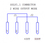
Also skip the Kelvin 4wire output mode that the SSLV offers. Make it two wire conventional mode which is more immune to electromagnetic interference for long cable runs. It keeps the voltage sensing loop area contained to the regulator's PCB only. See my attachment on how to do that by adding short insulated wire links soldered under the board at the pads of its output connector pins.
Since it will be serving as a remotely located PSU to the main unit which has extra DC circuitry between its power input and its pre-pre circuit, there are no direct nodes of interest to sense anyway.
Since it will be serving as a remotely located PSU to the main unit which has extra DC circuitry between its power input and its pre-pre circuit, there are no direct nodes of interest to sense anyway.
Attachments
OK, thanks for that guidance. I copied and pasted the info into my notes on the SSLV.
I'm sorting things out with Tea now. It looks like if I want to have the option to put together SSLV supplies for all three projects that I will need to order 3 of the SSLV boards in order to have a positive and negative rail for each supply.
The mini DSP can run anywhere from 5-24Vdc and needs 150mA according to the manual. The BoozeHound Phono runs on 18-24Vdc and supposedly uses less than 50mA, but I think it's prudent to give it the ability to supply 100-150mA.
The ZYX CCP-1 needs 12V, and I'll be running the mini DSP at 12V and the BoozeHound at 18V. So I guess I will need 3 each of the positive and negative rail mini kits with the IRF9530/530 option? I realize there are other items I will need to come up with to set the voltage for each supply properly.
- Status
- This old topic is closed. If you want to reopen this topic, contact a moderator using the "Report Post" button.
- Home
- Amplifiers
- Power Supplies
- The simplistic Salas low voltage shunt regulator