Impatient as I am, changed all non passive components starting from Q303 to the output.
I gave a try with the dummy load and worked fine. Connecting the regulator to the load, to my surprise, same situation as before.
And the culprit was a loose connection from the regulator ground to the DAC :-(
Very robust design I must say.
Works fine now, thanks for the hint.
I gave a try with the dummy load and worked fine. Connecting the regulator to the load, to my surprise, same situation as before.
And the culprit was a loose connection from the regulator ground to the DAC :-(
Very robust design I must say.
Works fine now, thanks for the hint.
Last edited:
Hi Kazuo
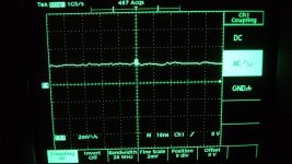
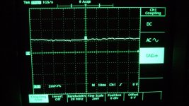
Better set the probe at 1X and turn the Tek TDS scope's 20MHZ bandwidth limit "ON".
Thanks for advice
")
Since I am experimenting on some MOSFETs for M3, I will take photos after finished again.
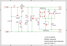
Reflektor Advanced
Hi, Canvas
I have to apologize to you.
On post #5934 I said that MTP3055VL was not suitable for M3.
However, I thought that this opinion was on no grounds and must be tested.
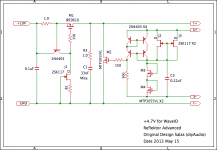
As result, MTP3055VL shows better performance than STP55NF06L,feeling more liveliness. I guess this reason is its lower Cxxx.
Yes, I recommend MTP3055VL.
I thank you for letting me noticed
Attached are latest schematics, more simple circuit than previous.
Kazuo san,
I'm glad you've improved the reflektor. I am planning to try the new version. However, I don't have STP55NF06L at hand. Can I still use MTP3055VL as M3?
Hi, Canvas
I have to apologize to you.
On post #5934 I said that MTP3055VL was not suitable for M3.
However, I thought that this opinion was on no grounds and must be tested.
As result, MTP3055VL shows better performance than STP55NF06L,feeling more liveliness. I guess this reason is its lower Cxxx.
Yes, I recommend MTP3055VL.
I thank you for letting me noticed
Attached are latest schematics, more simple circuit than previous.
Attachments
Quick question regarding Current Set resistor for SSLV reg.
Hi,
I've got a 'SSLV' board here from dvb-projekt to use as a 5V supply for a load that draws 500mA.
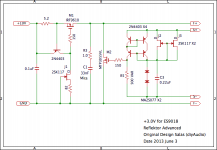
The BOM that came with the board specifies (R1) as 10ohms and has 'Adj Current ~200mA'.
From what I've read in this thread, R1 to set current should be 0.6/current required. Where current required equals load current plus ~200mA for the shunt.
I calculate therefore 0.6/0.7 = 0.85 ohm (or closest value), in a package that can accommodate (0.7x0.7)x0.85 = ~0.5W. (3W+)
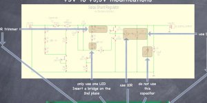
I have seen a few different schematics around which may or may not make a different, I have attached the circuit that I am using, current set resistor is to the left 'R1', I'm not using 3v3 output but its the only schem. that I have.
If someone could varify that my calculations are correct (and perhaps also that the shunt is OK with 700mA in the event that the regulator is unloaded), that would be very much appreciated..
Thank you,
Shane
Hi,
I've got a 'SSLV' board here from dvb-projekt to use as a 5V supply for a load that draws 500mA.
The BOM that came with the board specifies (R1) as 10ohms and has 'Adj Current ~200mA'.
From what I've read in this thread, R1 to set current should be 0.6/current required. Where current required equals load current plus ~200mA for the shunt.
I calculate therefore 0.6/0.7 = 0.85 ohm (or closest value), in a package that can accommodate (0.7x0.7)x0.85 = ~0.5W. (3W+)
I have seen a few different schematics around which may or may not make a different, I have attached the circuit that I am using, current set resistor is to the left 'R1', I'm not using 3v3 output but its the only schem. that I have.
If someone could varify that my calculations are correct (and perhaps also that the shunt is OK with 700mA in the event that the regulator is unloaded), that would be very much appreciated..
Thank you,
Shane
Attachments
Tack in a temporary 10r for the current setting resistor.
Measure the voltage across it and from that determine the CCS current.
*** more 10r for extra CCS current.
Each time you add an extra "R" the voltage will drop very slightly. Recalculate the CCS current.
When you get to close to what you require power down and replace the group of 10r with an equivalent single resistor, or leave the group of 10r soldered in permanently.
Thanks Andrew, is there an amount of current that the shunt requires before it functions correctly?. If the circuit does comply with R1 = 0.6/Current required, 60mA isnt alot for a cct that I hope will be ok with 700mA through the shunt itself in the event of the supply being unloaded.
Measure the voltage across it and from that determine the CCS current.Tack in a temporary 10r for the current setting resistor.
Measure the voltage across it and from that determine the CCS current.
*** more 10r for extra CCS current.
Each time you add an extra "R" the voltage will drop very slightly. Recalculate the CCS current.
When you get to close to what you require power down and replace the group of 10r with an equivalent single resistor, or leave the group of 10r soldered in permanently.
Add more 10r for extra CCS current.
The blotted out word is "add". What's wrong with that@?
Hi Kazuo
Better set the probe at 1X and turn the Tek TDS scope's 20MHZ bandwidth limit "ON".
I measured again.
Probe is set at 1X. You can read other conditions from photos
Attachments
Hello Kazuo
Thanks for the captures. They look appropriately tame and quiet. Do you manually run the base line at one graticule above the centre for clarity, or it jumps there by itself?
Your eyes do not miss any small things
I purchased TDS350 that was secondhand and no maintenance at bargain price. I guess it needs adjustment. This may be the reason of not matching base line.
I have downloaded the manual and reading how to adjust.
It would be nice if it can run a self cal routine as all the more recent DSOs.
Thanks all.
After running self test mode, TDS350 was adjusted correctly
Reflektor Advanced
On post #5934 Mr. Canvas let me notice that Cxxx of M3 NMOSFET is important factor. I guess lower the Cxxx better the sound. However Cxxx of NOSFET is relatively big. Therefore I decided to look for a higher-performance device for NMOSFET.
Now I have replaced NMOSFET with RF diode. I got MA2S077 which Cd is 0.9pF (typ). Unfortunately it is discontinued. But you can find the substitution easily. Measuring serial resistance (Rs), it shows approx 2 ohm/each on 10mA DC. The Rs tends to become lower over high band frequency.
The sound is more open, transparency and soulful, obtained a big improvement IMO.
I think that Reflektor is affected greatly by two factors at least.
1) The quality of C1
2) The quality of R5
If you use lower quality one you would feel dissatisfaction by all means and could not know the true talent of Reflektor. As long as I used some film caps for C1 and/or winding wire resistor for R5, I was not able to obtain a good result. I recommend that Teflon or Mica for C1 and Vishay VAR for R5.
Next I will study how the quality C3 affects the sound.
best regard
Attachments
- Status
- This old topic is closed. If you want to reopen this topic, contact a moderator using the "Report Post" button.
- Home
- Amplifiers
- Power Supplies
- The simplistic Salas low voltage shunt regulator