Hey all,
I've read good things about this shunt regulator and decided to use one as a supply for a Joachim Gerhard Buffer. The buffer requires +/-15v and 25mA per channel. The things I'm looking to accomplish are: what should I use BJT or IRF? and would this... http://www.digikey.com/scripts/dksearch/dksus.dll?vendor=0&keywords=TE62055 ...work for a transformer? Amveco makes a dual 18VAC version as well, but from my reading of the BiB guide it looks like the dual 22VAC version would be a better choice.
@Salas I saw your response... http://www.diyaudio.com/forums/powe...-voltage-shunt-regulator-116.html#post3402287 ...about how to pick a transformer. I'm still trying to wrap my head around this. I'm a bit of a beginner on the design side of things and have had my hands dirty for quite a bit when it comes to "paint by numbers" electronics. This is my first foray into trying to get out of that box.
Thanks,
Scott
Alright, see with what cap where does least possible Vpp of whatever circulates or emits and you can't do much more, then leave it alone.
I have added a 1000uF FR cap on the shiga entry and things are down to
No patience right now to experiment with lower values and different types...
When I start wrapping things up, I will also up the CCS current a bit
Hey all,
I've read good things about this shunt regulator and decided to use one as a supply for a Joachim Gerhard Buffer. The buffer requires +/-15v and 25mA per channel. The things I'm looking to accomplish are: what should I use BJT or IRF? and would this... http://www.digikey.com/scripts/dksearch/dksus.dll?vendor=0&keywords=TE62055 ...work for a transformer? Amveco makes a dual 18VAC version as well, but from my reading of the BiB guide it looks like the dual 22VAC version would be a better choice.
@Salas I saw your response... http://www.diyaudio.com/forums/powe...-voltage-shunt-regulator-116.html#post3402287 ...about how to pick a transformer. I'm still trying to wrap my head around this. I'm a bit of a beginner on the design side of things and have had my hands dirty for quite a bit when it comes to "paint by numbers" electronics. This is my first foray into trying to get out of that box.
Thanks,
Scott
The SSLV1.1 (Back In Black) guide has most stuff you need to know. You just get a GB board and you are sorted. Both 18+18 or 22+22 VAC Tx are good for your purposes. That example is about 35V scale so choosing VAC about equal as VDC needed covers a 10V drop which is good for lower capacitance in the CCS MOSFET and covers logical mains variations from place to place or hour to hour services.
I have added a 1000uF FR cap on the shiga entry and things are down to

No patience right now to experiment with lower values and different types...
When I start wrapping things up, I will also up the CCS current a bit
It looks good VS what you initially got. Its no instability and you ate away much weird stuff you could pick so its a good thing. Plus the counter shows nothing specific.
It looks good VS what you initially got. Its no instability and you ate away much weird stuff you could pick so its a good thing. Plus the counter shows nothing specific.
To sum everything up and build some further understanding, we had ~200mV EMI that was playing tricks with the sense lines.
By capping the sense lines we slowed them down and saw the actual raw EMI as plain random noise, so we had to cap it to eliminate it.
We basically "limited" the sense functionality?
Try a Zener reference. Any, even 18V to check. If its not oscillation and the cap does not have a problem it should go Vz+VFled+2Vbe=Vo. Zener cathode orientation vice versa to LED.
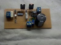
Here is one I made with the 3055VL. Target was to get 35 Vout. Vin was 43V. I had a problem in the beginning to get more than 15V with the 5K trimmer and I had to go up to 15 - 20K to reach the desired voltage. But could not get the voltage to be stable and not to drift. Maybe due to thermal issues (4404 too close to the heatsinks?), or due to my stash of 4403 which seemed to be higher Hfe. Changed the trim and led you see on the pictures (also removed the zip tie on the lower pair) with some combination of zeners and diodes and is stable right now. Also tried an 640 in place of the 3055VL but here was no difference in the drift.
Could not listened to it yet as I am too busy at the moment, will see when I get some time.
Attachments
thank you Salas and vgeorge
4403 are far away from Mosfets - I don't have heatsinks at all because I test only for 20 sec
I am almost sure that there Is no oscillation - why It will work to 14 V and not more
will see with a led string or zener
BTW I removed Vref filtering cap
4403 are far away from Mosfets - I don't have heatsinks at all because I test only for 20 sec
I am almost sure that there Is no oscillation - why It will work to 14 V and not more
will see with a led string or zener
BTW I removed Vref filtering cap
I would use inspired guesswork to suggest the Shiga has not got properly designed decoupling built in to the correct locations and of the correct sizes/types.I have added a 1000uF FR cap on the shiga entry and things are down to
No patience right now to experiment with lower values and different types...
When I start wrapping things up, I will also up the CCS current a bit
@ Vgeorge:
3055VL is under 2V VGS at that bias so it would take a big resistor. Still it climbed.
What I meant was that even with the 640, the resistor value was higher than what samoloko used.
I would use inspired guesswork to suggest the Shiga has not got properly designed decoupling built in to the correct locations and of the correct sizes/types.
You would probably be right...
I plan on separating some more stuff with their own PSUs... we ll see...
- Status
- This old topic is closed. If you want to reopen this topic, contact a moderator using the "Report Post" button.
- Home
- Amplifiers
- Power Supplies
- The simplistic Salas low voltage shunt regulator