Not really with such a big cap swamping it, if you mean connected like in the attached clip.
Exactly!
Thanks.
I have to confess that a very big reference capacitor, especially one with very low ESR, is a plus for regulator audio signature.
I used with success on that position 2200uF Panasonic FC. The regulator is used for a preamplifier with very poor power supply rejection.
Guys, i have searched the thread but did not find an answer.
I am at the optimization stage of my dac and thinking of tackling power supply impedance to the tda1541 and clock. Unfortuntely i am not in a position to measure output impedance in circuit (no money for a network analyzer).
So second best is simulations....I have seen the output impedance models posted over the years. However has anyone ever posted some info on optimizing the output impedance of the reg in conjunction with one or more decoupling caps? In digital we are looking at as low as possible into the >10mhz range..... Are there any tried recipes out there?
Guys, i have searched the thread but did not find an answer.
I am at the optimization stage of my dac and thinking of tackling power supply impedance to the tda1541 and clock. Unfortuntely i am not in a position to measure output impedance in circuit (no money for a network analyzer).
So second best is simulations....I have seen the output impedance models posted over the years. However has anyone ever posted some info on optimizing the output impedance of the reg in conjunction with one or more decoupling caps? In digital we are looking at as low as possible into the >10mhz range..... Are there any tried recipes out there?
You need to have an array of many caps, on a two-sided PCB with unbroken planes of copper on both sides (drill holes only, with denuded hole edges on one side of pcb, for cap leads). You'll have one of those as each power rail. They need to be shaped right, not long and narrow.
With a 10x10 array of 1000 uF electrolytics, and a 1mm thick FR4 board, you should be able to get the total inductance seen at the load down to less than 1 nH; probably to 0.5 nH.
You might want to use a daughterboard for your main circuit, with standoffs so it is straddling over the edge(s) of the cap array board(s) (depending on whether you need dual-polarity supply), so that all of the power and ground pins can go straight down through the duaghterboard and directly into the cap array board(s). [Or, of course, use a real multi-layer board, with caps distributed all over the board, and power and ground feeds distributed all around their layers.]
The illustrious Terry Given, electromagneticist extraordinaire, presented a prototype, with actual network analyzer measurements, and design guidelines, right here on diyaudio (His was for power amps. Maybe you can re-size caps as needed.).
I created a set of links directly to his posts about it, so people wouldn't have to search for them individually, and wouldn't miss any, which I put at the bottom of the post at:
http://www.diyaudio.com/forums/chip-amps/224914-lm3886-component-selection-3.html#post3282640
NOTE that in the first link, Terry meant to say RADIAL instead of AXIAL.
P.S. Also do a google search for papers and webpages by Henry W, Ott, Bruce Archambeault, Eric Bogatin, and others.
P.P.S. There are much-cheaper but more-labor-intensive ways to measure impedance, than a network analyzer.
Enjoy,
Tom
Last edited:
Hi Salas I have a st-1700a distortion meter. It has a 15volt plus/minus supply for each of the section osc. and detector . the raw voltage before the regs is about 35 volts+/- each rail . If I use your regs should I pre reg the voltage down to what ? Thanks for your view .
Hi all!
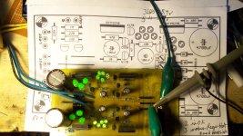
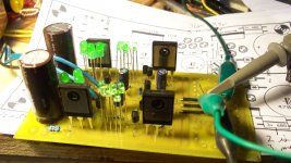
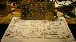
Got my mezmerizer working first try,lol.Rolled on the variac and all is well!
Waiting on some matched sk170 to land in the mail box and will finish the circuit,Both sides are at 10.3 works Perfect,lol.
Have a GREAT super bowl PARTY,I've got to start cooking and getting set up I wouldn't want a bunch of yelling hungy football fans yelling at the cook/bartender,We got plenty of home brew too .....I hope they don't fall a sleep during 45 mins of commericals,lol. got the al-ke-hol levels good and high in that beer lol.
THANKS SALAS!
have a good day!
NS
Attachments
Last edited:
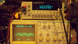
Very nice from scratch diy. Congrats. What is that 2.4mV RMS undulation on noise at ~16.5MHZ though? Too high to be a real product. A 150Meg scope should add its own noise floor more than any 20Meg one of course, but why wavy I wonder. Does it change if you remove the crocks to the TL71 DMM probes or dress the scope's probe differently? Is it there with the probe non end shorted when lying on the bench? What shows with 20 BWL pressed?
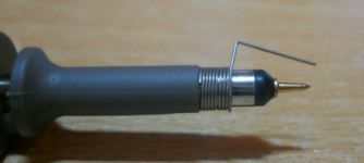
Measuring with the scope probe this way will always add some noise, in my experience. For critical measurements I always take the probe sheath off and use a very short solid copper wire from the scope probe to the load ground. Makes a big difference for sub-millivolt measurements. Hehe, your work brings back good memories. 
Attachments
- Status
- This old topic is closed. If you want to reopen this topic, contact a moderator using the "Report Post" button.
- Home
- Amplifiers
- Power Supplies
- The simplistic Salas low voltage shunt regulator