These are the sim curves for 1.2R and Reflektor (the two versions that fair better in that respect). A 1.1 reg was measured by a member on AP station up to 100kHz once and followed well, fairing a bit better than the sim actually. So the sims should be trustworthy enough.
Here is V1.1 sim:
Attachments
i use a selfregulating shuntregulator (very audiofiel)
the schematic is a bit the same .
because the current through the second transistor is regulated it is very easy to use .
schematic.
see shuntregulator 1
the schematic is a bit the same .
because the current through the second transistor is regulated it is very easy to use .
schematic.
see shuntregulator 1
These are the sim curves for 1.2R and Reflektor (the two versions that fair better in that respect).
Hi Salas,
& thanks for posting the simulation curves
")
It makes me think that combining the shunts with a capacitor with superb high frequency performance (e.g. low impedance) might be feasible, however, I noticed in another post that there were some reservations about using high capacity capacitors on the output... Can I ask you if this this is so or may I combine e.g. the reflector with high value low impedance capacitors?
And then another question pops up and that is if one of those who built these shunts have tried to submit the shunt to a square wave load so as to see how it fares with dynamic loads?
Thanks again for replying Salas - best wishes from Denmark
Jesper
The large output capacitor is going to restrict the open loop bandwidth and change the phase. Less OLG bandwidth means specific application purposes and less integrated total noise. Also means a slower regulator. It can possibly lead to redesign of sorts if it will make it oscillate. For the Reflektor use the STP type output Mosfet for best HF. You should try combining for yourself, haven't experimented with large output cap and Reflektor. Square wave load test has been done with 1.0 once.
Attachments
I tried On Semi MUR860 without caps vs IRF HEXFRED 8A with caps, and the 860 works alot better; less grainy in the treble and less distorsion in the rest of frequencies. I've to compare the 860 with vs without caps. Asap the answer.
Interesting, let us know your verdict.
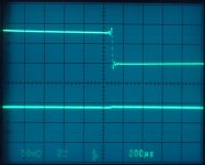
Square wave measurements ...
Hello again Salas,
& thanks for the image of the square wave load response ... I guess the 1.0's response is the bottom curve, right? And from the slope of the square wave it looks as if it's about a 50 kHz wave frequency ...
The response looks quite stable ... do you know which load (current) difference the square wave created relative to the constant current?
Greetings,
Jesper
I don't know if the flowing issue is covered or not in this long thread.
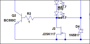
I have build an 18V BiB positive regulator and I discovered on the hard way, by fraying the reference voltage bias jfet, that in the case of a short circuit at the output of the regulator and medium to high reference capacitor (over 1000uF) we need a protection Schottky diode placed in paralel with jfet.
I have build an 18V BiB positive regulator and I discovered on the hard way, by fraying the reference voltage bias jfet, that in the case of a short circuit at the output of the regulator and medium to high reference capacitor (over 1000uF) we need a protection Schottky diode placed in paralel with jfet.
I have wrote in older times that a high value cap can kickback to the Jfet, normally not when under 470uF with Toshibas. I recommend 220uF in the 1.1 build guide for that so to avoid extra junctions in the ref. A J201 can fry at 100uf even in case of fault. Not only in short condition but on quick on/off cycling also.
I have wrote in older times that a high value cap can kickback to the Jfet, normally not when under 470uF with Toshibas. I recommend 220uF in the 1.1 build guide for that so to avoid extra junctions in the ref. A J201 can fry at 100uf even in case of fault. Not only in short condition but on quick on/off cycling also.
Do you see any problem if the jfet is reverse bypassed by a diode?
- Status
- This old topic is closed. If you want to reopen this topic, contact a moderator using the "Report Post" button.
- Home
- Amplifiers
- Power Supplies
- The simplistic Salas low voltage shunt regulator