hi,
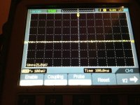
a quick question regarding v1.0 5VDC, I got 115mv pik to pik oscillations, is that fine?
They look like aperiodic glitches. No, not acceptable. Must be rid off. What exact circuit you made, and what is the load? Has anything extra parts on its rails? Is it a two wire PSU connection or 4?
Salas: But i would need a new PCB for that circuit? without cross checking schematics it looks like a completely new layout, which would need new pcb?
That is a special Reflektor. Its for you to make on a matrix. Something with boards for circa 100V could only be SSHV2 with smaller than 68K ref resistors if the max current demands are no more than 80mA.
Hi Salas,
I'm very newby here, i was searching for shunt regulator and finaly found this thread. Very big Thread and very very intersting.")
I'm looking for a +/- 15 to 22V shunt and 5V shunt,
what is the last version of the shunt (i saw V1.2 somewhere and the one in the page 562 called "reflektor 100" but it's look like something for High voltage)?
I saw 2 PIN called "sense" where do i have to put them?
Is there any "condensement" of these 563 pages? it is very intersting, you make a good work, very amazing, but I will pass my entier life to read all off them+all the outlink to look at.
May be a good idea is to make a new thread with/for each new version and/or a tutorial showing how to use the shunt/evolution/a kind of "Manual" of what have been done by you. May be you did it but i dont know where to search...
Sorry for the inconveniance, i dont want to be unpleasant with you (it's just a reflexion of a new becomer and almost afraid on this Big thread)
P.S. : Sorry for my bad english
Best regards...
Mike
I'm very newby here, i was searching for shunt regulator and finaly found this thread. Very big Thread and very very intersting.
I'm looking for a +/- 15 to 22V shunt and 5V shunt,
what is the last version of the shunt (i saw V1.2 somewhere and the one in the page 562 called "reflektor 100" but it's look like something for High voltage)?
I saw 2 PIN called "sense" where do i have to put them?
Is there any "condensement" of these 563 pages? it is very intersting, you make a good work, very amazing, but I will pass my entier life to read all off them+all the outlink to look at.
May be a good idea is to make a new thread with/for each new version and/or a tutorial showing how to use the shunt/evolution/a kind of "Manual" of what have been done by you. May be you did it but i dont know where to search...
Sorry for the inconveniance, i dont want to be unpleasant with you (it's just a reflexion of a new becomer and almost afraid on this Big thread)
P.S. : Sorry for my bad english
Best regards...
Mike
They look like aperiodic glitches. No, not acceptable. Must be rid off. What exact circuit you made, and what is the load? Has anything extra parts on its rails? Is it a two wire PSU connection or 4?
hi Salas,
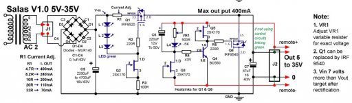
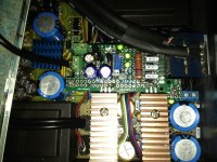
1. it is 1.0 version with 47uf Tonerex on the output (att) & BF245A as Q3
2. the load is two Wolfson Wm8740 chips
3. no extra parts
4. about 5cm coaxial cable (two wire)
5. no oscillations if I disconnect the load (pls see att)
Could someone please attach a scope screen to see how a decent Salas shunt reg should look like?
Attachments
Hi Salas,
I'm very newby here, i was searching for shunt regulator and finaly found this thread. Very big Thread and very very intersting.
I'm looking for a +/- 15 to 22V shunt and 5V shunt,
what is the last version of the shunt (i saw V1.2 somewhere and the one in the page 562 called "reflektor 100" but it's look like something for High voltage)?
I saw 2 PIN called "sense" where do i have to put them?
Is there any "condensement" of these 563 pages? it is very intersting, you make a good work, very amazing, but I will pass my entier life to read all off them+all the outlink to look at.
May be a good idea is to make a new thread with/for each new version and/or a tutorial showing how to use the shunt/evolution/a kind of "Manual" of what have been done by you. May be you did it but i dont know where to search...
Sorry for the inconveniance, i dont want to be unpleasant with you (it's just a reflexion of a new becomer and almost afraid on this Big thread)
P.S. : Sorry for my bad english
Best regards...
Mike
Hi Mike
This one looks like is the thread you need.
http://www.diyaudio.com/forums/power-supplies/192625-sslv1-1-builds-fairytales.html
It does not look you got a problem in your build, its stuff from the digital jumping on rail we may suppress better. What does the Wolfson have for rail to ground components where the 2 wires meet its board and beyond?
it has only a cap C38, the reg goes to 3 analogue supply pins only of the chip.
Attachments

His scope does not show a periodic waveform, just glitches here and there. I would take the 2 wires directly on C38 and see what happens by making it bigger or smaller, preferably using Tantalum cap.
hi,
sorry for late reply. Tried to remove C38 and found out that I've already removed it when connected the reg, so it looks very weird now. Should I add it and see if something changes
btw, there is another v1.0 shunt reg that works fine (no similar pics at all) and is connected to several opamps.
Happy New Year & new great projects to everybody

Hey Diy'ers,
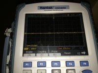
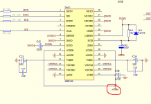
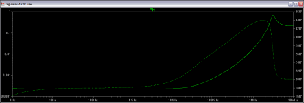
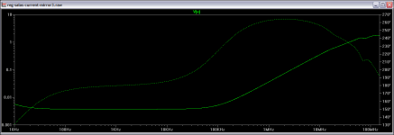
I've been following this thread with interest on & off for some time now yet have not seen any measurements/discussion about the HF (HF output impedance, i.e. e.g. 200 kHz to ~10 MHz) response of the shunt regulator. If this has been discussed might one of you guide me to the relevant posts?
Greetings,
Jesper
These are the sim curves for 1.2R and Reflektor (the two versions that fair better in that respect). A 1.1 reg was measured by a member on AP station up to 100kHz once and followed well, fairing a bit better than the sim actually. So the sims should be trustworthy enough.
Attachments
- Status
- This old topic is closed. If you want to reopen this topic, contact a moderator using the "Report Post" button.
- Home
- Amplifiers
- Power Supplies
- The simplistic Salas low voltage shunt regulator