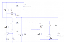
I have read a lot of this forum but not all, so I apologize if already answered. I have been trying to build a +/- V1.2R beta for a pre-amp I am building. Using a version of the F5 from Nelson only reduced currents to act as a pre-amp. Basically hope to replicate a B5 buffer as well all in one chassis. Have built a similar pre-amp for my son with a capacitance multiplier type of regulator which sounds great. I wanted to use a shunt regulator as have used before and liked their sound. To be honest, I have made some mods and use an SK170 instead of the 2N5457, dropped the 47k to 10k and use 100uF electrolytic to by-pass the 10k. I omitted the follower Q6 as the sk170's I have are around 8ma. I tried a follower and didn't make any difference. The current source part works fine. My problem: I cannot get the regulators to stay in regulation. The negative version is the more stable and starts up fine by itself but shortly afterwards the base of Q8 drops from .6 to a lower number and the source and gate of the pass device 9240 become the same value instead of the 4 volts difference. The positive side rarely regulates properly with the same issue and doesn't even start normally. They are conducting though as the current source is passing 333ma and both are well heat-sinked. I have replaced all the transistors several times to no avail. I use 750 ohms instead of the 1k but doubt that should be a problem. I use 4401 and 4403's instead of the BC series as I have lots of them. I have 120uF electrolyic on the output. and have tried various zobels. In or out they make no difference. I have been fighting this for several weeks so I am asking for some help. I suspect oscillation and my scope recently died so that is no help. I use the ground plane frog style for my work which has never been a problem for me. I do have a load attached and makes no difference whether in or out so doubt that circuit is the problem. If you can point me to a post that would help. Any suggestions. I don't really want to go to the Reflector but may have to.
Not good at drawing schematics but basically the same as your V1.2R with Q6 removed. Using 560 ohm as gate stopper on the Fet. 750 instead of 1K for R10 and 10k and 100 for R11 and C1. Moved R6 to the unregulated B+ to make sure the current source would start. Will move back when stable. Used .1uF PP at the unregulated as still bread-boarding and using aligator clips from PS. PS pretty much a stock Pass with CRC and R .22 with 40,000uF. Thanks for the quick reply. Suspect in need some pf somewhere and sometimes get about 7mv of AC when both positive and negative connected. < than .1mv when only use one-side. Must be some positive feedback somewhere.
")
Thanks for your quick reply and also RCruz for your interest. This is a most helpful forum. I certainly intend to reconnect the bias chain to the regulated output when I get it stable. For the record I use an LM336-2.5 Instead of the led and by-pass it with a 1uF PP. I am pretty sure the CCS part of this is ok. I am busy with work most of this week but when I get a chance i will put in the degeneration resister. I plan to continue to use the IRFP9240 as I have quite a few of them. I use a 500ohm trimmer and when it works is around 100ohms with my 170. Again thanks for your interest and I will let you know how it goes.
Hi submediterraneum guys, and rest of the world, of course, I've just tried an R core tx from Selectronic to power a TPA Metronome (upsampling device). The tx feed a hexfred diodes bridge and a 12r at 13Vin and 7Vout.The R core tx, respect to
Talema toroid, is more clear,trasparent, dinamic and with more silence between the musical passages. An upgrade on all the line! Then I tried the R core also to power my Buffalo II (also with 12r), but this time the suond was boring, without dinamic,uninvolving at all. A very strange thing! Anyone have compared toroids vs R core?
Talema toroid, is more clear,trasparent, dinamic and with more silence between the musical passages. An upgrade on all the line! Then I tried the R core also to power my Buffalo II (also with 12r), but this time the suond was boring, without dinamic,uninvolving at all. A very strange thing! Anyone have compared toroids vs R core?
In analogue it is as you describe in the first experience. About variations in digital I am not learned by application. Are there different brand/type diodes/capacitors in the two occasions you experienced so it could be a matter of synergistic or antagonistic subjective properties mix?
Normally the R core gives better mains isolation due to completely separate primary and secondary and much less cross capacitance than the toroid. It passes strict regulations for isolation in medical equipment and most models have electrostatic shield too. Its the yellow primary wire. Do you earth that along the mains earth to chassis?
I connected the yellow wire to a dedicated earth ground, but in this way sounded worse.
My system is completely disconnected to earth ground.
Wich version are you using?
Can you see any differences when applying the R Core in the good subjective influnce and bad subjective influence circuits situation when having an oscilloscope on the raw dc rails watching filter capacitors charging cycle? It could have lower impedance as a Tx than your previous.
1.2r
Have you tested with a scope the reg?
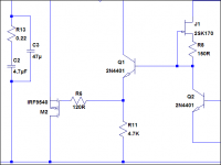
To cut a long story short, that config you got will not work. Try this mix with the parts you described. R7 can be your trimmer.
I wish to apologize for wasting your time as the fault was in my unfinished circuit and not your regulator. AS you know my plan was to build a version of the B5 active crossover based on Nelson's design. I use Lowthers and the large woofer on an open baffle. My Lowther amp is a current amp based on the F3 and the gain is around 20bd and I have an F5 amp for the woofer. I have been using a version of the basic B1 buffer and need a bit more gain so planned on using the F5 design slimmed down as in the Burning amp 3 front end but with feedback of 50 ohms to give a gain of 14db. I use the Toshiba Fet's as mentioned in his article. This part of my design was completed. This will give 4 outputs. A direct line output for driving an amp directly, an output for headphones, an output to drive the high pass crossover and the last output to drive another F5 stage to give a gain of 20bd and do the low-pass crossover for driving my woofer. This latter stage will have an attenuator to allow for adjustment and the input to the first will have the volume control for the whole system. I had mounted the second amp fet's , cascode BJT's and the output fets but had not hooked them up. I did however puit in the .47 ohm source resitors to the output fet's and had the drains connected. I did not have any gate connections. The problem was that even though I thought this was open and would have no effect this output fet string was causing the oscillation. I opened the source resitors and the regulators are rock steady and the input first stage amp is running perfectly. I can usually get down to 1-2mv offset and it stays there so I am quite happy with this. I am not an engineer so can't explains why this should have happened but am happy to report the regulator was not the problem. I have made the changes though as suggested above and will put R6 back to the regulated side and probably will leave it as Salas suggested and leave the follower transistor out. I dropped R8 to 47 ohms to get the current up a bit to drive the Fet capacitance. Running about 3.5ma with this and seems very stable. Can't listen to it for a while as I have the other channel to build and then connect it all up. Thanks for you help though and you live and learn.
Tom
- Status
- This old topic is closed. If you want to reopen this topic, contact a moderator using the "Report Post" button.
- Home
- Amplifiers
- Power Supplies
- The simplistic Salas low voltage shunt regulator