Have another question: If I was building a 18V Reflektor, I could use Vgs=4, R6=1200 and Rvar=4.38k. Alternatively I could use 2 LED's to set LEDVf=4 and change Rvar to 3.78k.
Is one route prefered over teh other or are they equal (besides the trick of getting those exact resistor values?)
Is one route prefered over teh other or are they equal (besides the trick of getting those exact resistor values?)
The led is there for thermal comp and indication. You can use a diode if you don't care about indication and reduce a fixed parameter. Don't use two, it will start drifting down more. Don't change R6 than 1000R or about, its the source impedance that drives the gate, also a load to the mirror and there are gain phase implications. Use 4/5 of a value in fixed resistance and just 1/5 in trimmer part is a nice method. Resistor characteristics dominate that way and you have freedom to fix top part of Vo in detail.
On which schematic the designations you talk refer to? If you will run a noise simulation you will see the problem with 10n. Its not only about impedance. Use a compact electrolytic 16V with very low ESR & HF impedance 1000uF if you plan for digital. That can filter deeply and have good impedance on low VrefR also. You can find a multitude of computer motherboard capacitors offered cheaply with those characteristics. For J3 in the schematic you show here K170BL can do because in low voltage its high idss will not overheat Q18. Although I would prefer you cut its idss down to 2mA with a resistor for Q18 to work in a less noisy manner. If the other position you refer to is some common gate top half of a cascode CCS to another K170 , forget it, you need double the Vgs and up, for top half. So to have some Vds for bottom. Try a J310 or BF245C.
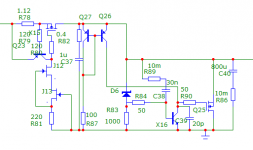
I was referring to the original schematic V12R positive low voltage (post #3200). I don't know about noise yet, thanks for the info. So, even with 2sk170GR as J4 here, noise will be high with low R39? What is VrefR here? I plan it for audio, will Nichicon NU 330uf capacitors (or Nichicon L8 for 5v) be better/suitable? Or a PP caps only?
Yes, other position is different fet in the CCS.
C29 here seems to me (in simulation) lowers peaking of impedance in the 1 mhz region, about 100-1000pf
OK, makes sense. Apologies if these questions have been asked before. Perhaps we should set-up an FAQ?
What determines Vmax? Is it = to Vin-5V? And what is deteremining the 5V?
Can you recommend MOSFETS and transistors for a 100Vin, 75Vout?
Then also for a 75Vin 38Vout?
Can we use 2sk170 in these as well?
What determines Vmax? Is it = to Vin-5V? And what is deteremining the 5V?
Can you recommend MOSFETS and transistors for a 100Vin, 75Vout?
Then also for a 75Vin 38Vout?
Can we use 2sk170 in these as well?
If he will use 100 Ohm between g&s on an average BL to go ~2-3mA, the contribution is going to be 0.18uV for 20kHz BW
All variants for R40 here:
43 ohm for sk170GR, 104 for BL, 134 for V
or if R39 is 4k
155 ohm for sk170GR, 275 for BL, 330 for V
maybe some suitable?
Also, what about this schematic? Its like an reflektor+one bjt, higher gain? How about it?
Attachments
Found the following helpful guidelines:
"You can give it 30V absolute max raw DC input and 24V out. The stop is the top cascode Jfet that has 25V max. By the time the input Mosfet drops there is about Vin-5V potential for the top Jfet. If you watch that or you got a higher max device it can go higher, no problemo. If you can find BF245C which is 30V device you could be safer for input max due to mains and trafo uncertainties regarding max raw dc input and distance to output for solid regulation."
Post 4614
http://www.diyaudio.com/forums/powe...-voltage-shunt-regulator-462.html#post2774077
I was referring to the original schematic V12R positive low voltage (post #3200). I don't know about noise yet, thanks for the info. So, even with 2sk170GR as J4 here, noise will be high with low R39? What is VrefR here? I plan it for audio, will Nichicon NU 330uf capacitors (or Nichicon L8 for 5v) be better/suitable? Or a PP caps only?
Yes, other position is different fet in the CCS.
C29 here seems to me (in simulation) lowers peaking of impedance in the 1 mhz region, about 100-1000pf
With GR things will be more balanced. Q18 working more relaxed on lower current CCS load and no degeneration resistor as with BL.
VrefR is R39 2k in your schema.
PP caps have least THD but their filtering effect is modest due to value and bulk limits. A good electrochemical capacitor will be best for noise, and what is priority depends in your client circuit's gain and PSRR. Clever RC bypassing for no resonances can make an electro more subjectively transparent. C29 may add AC feedback but impact of add on you will see in real layout and stability. Which can be difficult with 1.2R to succeed. It can take you iterations.
OK, makes sense. Apologies if these questions have been asked before. Perhaps we should set-up an FAQ?
What determines Vmax? Is it = to Vin-5V? And what is deteremining the 5V?
Can you recommend MOSFETS and transistors for a 100Vin, 75Vout?
Then also for a 75Vin 38Vout?
Can we use 2sk170 in these as well?
Vin-5V requirement is to give the CCS space to work properly in series.
I had a preamble on how to scale it when I presented it but I will make you an example schematic with proper transistors to make things easily understood ASAP.
All variants for R40 here:
43 ohm for sk170GR, 104 for BL, 134 for V
or if R39 is 4k
155 ohm for sk170GR, 275 for BL, 330 for V
maybe some suitable?
Also, what about this schematic? Its like an reflektor+one bjt, higher gain? How about it?
Just use one of your lower measuring GR without any drop idss resistor if you can't readily get say a BF245A or 2SK30Y 2N5457 etc.
The schematic is a basic reflektor hybrid with a CFP, it may oscillate on you terribly or it may not, I can't comment expertly on something not made yet. You may make it and let us know. Some day I will test the REFLEKTOR X idea I have in mind for about a month now for more theoretical performance with less parts than that. If it will work stably and I find it really adds subjectively too then it will only pass. Both demands are difficult.
Or should I name it ZERKALO X inspired by the groundbreaking Tarkovsky film?")
"The Mirror" trailer - YouTube
"The Mirror" trailer - YouTube
I recommend you build 1.1, reflektor, 1.2R, see their layout conditions, measure them, see they are stable on the rails with your load applications, listen to them carefully so to form your idea of what road you like and then test inspirations on them. They are a nice hobby because they contribute soul to known applications and aren't that expensive or big to play with, recycling parts between them even.
I had a preamble on how to scale it when I presented it but I will make you an example schematic with proper transistors to make things easily understood ASAP.
Thanks Salas, that would be a great help.
Ryan
C1 is the main filter electrolytic on top section drawing, maybe you meant C2 its bypass? I don't recommend random bypassing especially without instruments, avoid. Electrochemical caps alone will do fine. Its just in many drawings 0.1uF get sprinkled around ideally. But things aren't ideal, can resonate. C1 can be a Nichicon KG.
Use output cap 220uF Nichicon, Elna, Panasonic, not LowZ series any you may get easily. 105C are welcome if near the sinks. C4 Vref filter cap can be Silmic II, Nichicon Muse or Fine Gold.
Just a quick message to say thanks for your help again Salas - the shunt reg is finished and has really lifted the already good performance of my 'Audio Widget' USB DAC. Always amazes me the difference a well implemented psu can make! Thanks for a great design
John.
Nice. Did you use a Nichicon gamut or a various brands mix?
I used 4700uF Nichicon KG with Qspeed diodes, and on the shunt PCB 220uF Elna Cerafines. Been very impressed with the latest black-skinned versions of the caps. Guessing they've been subtly improved over the years. Actually prefer these to Black Gate standards now. Looks like I got lucky with the component synergy - really powerful, but natural reproduction. Hugely involving. Dare I say it, the DAC is sounding pretty damn close to well mastered vinyl now
- Status
- This old topic is closed. If you want to reopen this topic, contact a moderator using the "Report Post" button.
- Home
- Amplifiers
- Power Supplies
- The simplistic Salas low voltage shunt regulator