They are not far from 220uF. Make sure its stable on the scope, bcs ZLH is very low impedance. Don't use C6, its wrongly added in that drawing.
I don't have a scope alas Salas. I guess that being the case I should wait and order a pair of 220uFs then? Any brands/types recommended which would be suitable in terms of impedence?
I've left C6 free. Is C1 ok to populate? I have an Arcotronics 0.1uF Polypropylene I could use here.
Cheers.
I don't have a scope alas Salas. I guess that being the case I should wait and order a pair of 220uFs then? Any brands/types recommended which would be suitable in terms of impedence?
I've left C6 free. Is C1 ok to populate? I have an Arcotronics 0.1uF Polypropylene I could use here.
Cheers.
C1 is the main filter electrolytic on top section drawing, maybe you meant C2 its bypass? I don't recommend random bypassing especially without instruments, avoid. Electrochemical caps alone will do fine. Its just in many drawings 0.1uF get sprinkled around ideally. But things aren't ideal, can resonate. C1 can be a Nichicon KG.
Use output cap 220uF Nichicon, Elna, Panasonic, not LowZ series any you may get easily. 105C are welcome if near the sinks. C4 Vref filter cap can be Silmic II, Nichicon Muse or Fine Gold.
On a different subject, has anyone tried to use(one section) of these regs for the Pass JFet BOZ? Since it requires less than 20ma, would you really need the power Mosfets? It is such a simple circuit, it really shows up the character of the p/s reg used. So far I keep going back to a 18v battery supply, everything else "gets in the way" of the sound.
C1 is the main filter electrolytic on top section drawing, maybe you meant C2 its bypass? I don't recommend random bypassing especially without instruments, avoid. Electrochemical caps alone will do fine. Its just in many drawings 0.1uF get sprinkled around ideally. But things aren't ideal, can resonate. C1 can be a Nichicon KG.
Use output cap 220uF Nichicon, Elna, Panasonic, not LowZ series any you may get easily. 105C are welcome if near the sinks. C4 Vref filter cap can be Silmic II, Nichicon Muse or Fine Gold.
Thanks for all that Salas - much appreciated! And yes sorry I meant C2 (which I shall remove). I'll order the other caps now.
Many thanks
")
Depends on Idss but 82R should have about he same effect as 75R on dropping it. So use it.
Don't change the R on the Zobel, its the damping that can change the phase margin a lot. With the cap is the frequency, you may wander a bit when still stable.
Yes, 100-200R can work but if you have to deviate better go towards 100R.
Don't change the R on the Zobel, its the damping that can change the phase margin a lot. With the cap is the frequency, you may wander a bit when still stable.
Yes, 100-200R can work but if you have to deviate better go towards 100R.
The setting resistor should not be allowed to fall bellow 1/3 of its opposite 1K resistor, the one between the Mosfet's gate stopper and ground. Thus 330R run by about 4Vgs/1K=4mA mirrored, gives 1.32V. Add 2V from the LED and two 0.7Vbe from the right branch mirror BJTs. That gives you the near 5V base. I would expect 4.7-7.4V with 1K VR. Tolerances or some problem may have squeezed that to 5-6V? We should know the practical Vgs, LedVf and Vbe in a build to see if it computes.
Hello,
If placing V1.2R LV sensing part near load circuit, big in size C1 (4.7uf) becomes an issue.
Can it value be greatly lowered, to 10n, and for low output impedance R10 also lowered, from 27k to 2k, and R9 adjusted? See attachment for 5v output. It simulates ok, near DC impedance only about 1.5-2 times bigger than with big C1. Does it has negative effects?
Also, what limiting use of 2sk170 as q8 and q3? (For output 5-15v, input 12-23 v)
Attachments
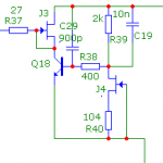
On which schematic the designations you talk refer to? If you will run a noise simulation you will see the problem with 10n. Its not only about impedance. Use a compact electrolytic 16V with very low ESR & HF impedance 1000uF if you plan for digital. That can filter deeply and have good impedance on low VrefR also. You can find a multitude of computer motherboard capacitors offered cheaply with those characteristics. For J3 in the schematic you show here K170BL can do because in low voltage its high idss will not overheat Q18. Although I would prefer you cut its idss down to 2mA with a resistor for Q18 to work in a less noisy manner. If the other position you refer to is some common gate top half of a cascode CCS to another K170 , forget it, you need double the Vgs and up, for top half. So to have some Vds for bottom. Try a J310 or BF245C.
Although I would prefer you cut its idss down to 2mA with a resistor for Q18 to work in a less noisy manner.
Any degeneration resistor will increase noise not vice versa. Moreover, jfets are less noisier at higher currents
- Status
- This old topic is closed. If you want to reopen this topic, contact a moderator using the "Report Post" button.
- Home
- Amplifiers
- Power Supplies
- The simplistic Salas low voltage shunt regulator