To avoid drift measures resistance in the trimmer & change for a low ppm fixed resistor. Do you have a scope? if yes see if with the 47uF near the DAC you have ripple or oscillates, if I remember well all shunt regs designed by Salas don't like a cap between the reg & the load.
thanks!
caps have been removed as adviced. Unfortunately do not have any scope, planning to get one in the following month...
Regarding the voltage, not sure if swapping trimmer to fixed resisitor will help as I have also negative rail with the same pot and there is no voltage raise at all. Also notice that with closed lid of the DAC, case becomes very hot (about 50-55 c inside) and the output voltage raises up to 5.25vdc, though negative rail stays the same...
what could that be?!
JFET's Tc in your hot box. Try BF245A Q3.
thanks, I'll try it.
could you please elaborate a bit more about 5mA IDSS, not sure if I got it

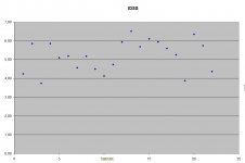
tried to match 3 sk170GRs and came out with 4.86, 4.88 and 4.94mA. Soldered them back, turned the reg on, adjusted trimmer to 5vdc output and closed the lid of the case. After about 15min I still got 5.20vdc...weird.
then I put BF245A as Q3, adjusted the legs as it's not pin to pin replacement, same with vdc output and closed the lid...after some 10min I got 4.89vdc it'seems that it's affected vice versa by the heat. Anyway I was unlucky again.
Is there any other suggestions? Perhaps if I use two decent BLs with 7-8mA IDSS as was adviced in some other thread + BF245A as Q3 that would stabilize the output vdc?
Accoring to the manual WM8740 DAC should work fine with +-10% of 5vdc, thus maybe it's not so crucial as it is now?
then I put BF245A as Q3, adjusted the legs as it's not pin to pin replacement, same with vdc output and closed the lid...after some 10min I got 4.89vdc
it'seems that it's affected vice versa by the heat. Anyway I was unlucky again.Is there any other suggestions? Perhaps if I use two decent BLs with 7-8mA IDSS as was adviced in some other thread + BF245A as Q3 that would stabilize the output vdc?
Accoring to the manual WM8740 DAC should work fine with +-10% of 5vdc, thus maybe it's not so crucial as it is now?
Q3 is the crucial component. With BF245A you went off only -0.11V you report. Why not adjust at 5.1V and then let it drift to 5V? Its the LEDs and the Vbe of the BC550 they act in tandem with Q3, and the PPM of the trimmer. Your manual gives 4.5V-5.5V tolerance, in other words why bother for 0.1V?
... in other words why bother for 0.1V?
indeed, it's pretty negligible in this case. I was just wondering why does it happens (thanks for explanation) and why nobody reported the same bahaviour.
And... minus drift is safer.
yes, thanks again for the help, Salas, and great reg!
The Leds are diodes, they show negative tempco, a few mV/C each. Its a balance of counteraction with the other semis. At 55C box interior your drift is fine IMHO. This reg isn't designed around a precision voltage reference concept, but around a minimalistic discrete one. We can be very careful about a Jfet type and sample and its zero tempco bias point, the exact drift of the whole system including Vbe & Vgs and the number and type of diodes, Leds etc so to minimize drift, but -0.1V in a hot box it can easily creep in again and its fine for audio purposes IMHO. I am sure all get some drift if they look for it, but you got a hot box interior that others may not. They may be using lower ppm resistors too. Its not a chip to tightly control the spot temperature each semi has anyway, its discrete and biggie with through hole components.
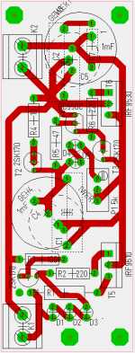
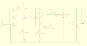
is this a correct interpretation of Salas 1.0 sslv
I want to use this schematic and this pcb for salas V 1.0 with IRF9610,9530 instead of IRF9240 for low current loads like DAC,Clock,Buffer,Phonopre. is this schematic correct for this applications and the pcb design ok? the pcb is from myself and i tryed to get it small as possible for my small chassis. the salas sslv bib is to big for my application. for dirct use i dont need the sensing feature.
thanks for your attention and help
kokonut
Attachments
- Status
- This old topic is closed. If you want to reopen this topic, contact a moderator using the "Report Post" button.
- Home
- Amplifiers
- Power Supplies
- The simplistic Salas low voltage shunt regulator