Excuse me for this annoying and maybe repeated question, but can the transistors from the original schematics (like 2SCK170 or IRFP9240) be substituted with others - how critical is it? I plan using these shuns for the 3.3 and 5V rails for my DAC.
read on from around 3 pages back for 3.3V
")
Help
Now I have come so far in my adventure that I have all 6 shunts in a box and connected for testing purposes. All 4 plus shunts work fine and one of the minus ones. The last one I can't seem to get adjusted higher than -3.9V. The working one is possible to adjust to -2.4V.
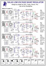
I have based the circuit on the following schematic
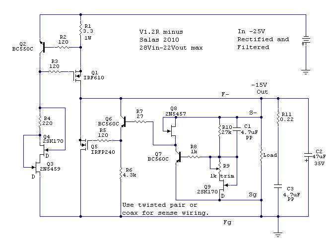
From there I have changed Q5 to a BD245C as I had some lying around, R10 to 6.8K and R6 to 1.5K based on reading and some testing with the circuit
Is there anyone that have an idea what could cause this?
Now I have come so far in my adventure that I have all 6 shunts in a box and connected for testing purposes. All 4 plus shunts work fine and one of the minus ones. The last one I can't seem to get adjusted higher than -3.9V. The working one is possible to adjust to -2.4V.
I have based the circuit on the following schematic
From there I have changed Q5 to a BD245C as I had some lying around, R10 to 6.8K and R6 to 1.5K based on reading and some testing with the circuit
Is there anyone that have an idea what could cause this?
first of all, what shunt mosfet are you using? (seems i cant zoom on the picture.maybe a jpeg format will help..?or what post is that schematic on?)
second, higher than -3.9 is toward zero or toward more negative voltage?
and maybe a picture of the actual built circuit might help spot potential problems.
second, higher than -3.9 is toward zero or toward more negative voltage?
and maybe a picture of the actual built circuit might help spot potential problems.
Last edited:
Hi,
After having greet success with a 5V build of a SSLv1.1 with BJT for feeding the analog side of a DAC chip, I plan to try a +15V/-15V SSLv1.1 with MOSFET for powering a dual Opamp. I do not know where to start for C102,C104 capacitors type and values, I think i also will have to reduce the local decoupling near the opamp (now 22uF tant // 0,1uF) ?
Any hint would be appreciated !
Thank you,
Maybe your q9 has much IDSS. Try for lower Vo by paralleling 10K to R10.
Tried that now, did not help but worth a shot, thanks Salas for the tips. Then I remembered that I had to lower R6 to get the voltage where I wanted it when testing the other one. Apparently I had to lower this one to 1k to get the desired voltage instead of 1.5k that I have on the other. I am warming heatsinks now to see if it is enough or if I have to rip the card out once more.
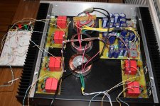
May I ask how you guys attach your pcbs as I had big difficulties getting the holes to line up both for the transistors and the pcb? Please excuse the cable salad in and around the box, connectors to be added and outputs/sensewires to be routed (hopefully tomorrow).
Attachments
Efkaristo poli Salas !
I only have 100uF or 1000uF electrolytics at hand, will one of those be OK for C101 ?
And for C103, is there a better choice than a 47uF electrolytic in my case ?
Parakalw (you are welcome). 100uF for 101 still OK. You can use the C104MKT+R1071R solution first, and only in case of instability you go for the C10347u+R107Jumper solution. First is faster.
So you had kept the voltage drop on R6 much and was blocking the low threshold. Very logical explanation.
One basic check is with scope so to know there are no riding oscillations on each reg since 1.2R is sensitive to layout. Did you use a scope?
I do not have a scope yet but it is probably my next investment. Seems it would be necessary to have one.
hi,
build mine according to 1.0 version (2 x 15 VAC, R1 - 2x33 Ohm 2w, VR1 2.5k). Works fine for +-12v for my preamp.
Just a quick question:
-is it typical that on positive rail I can get 5-12.5 VDC by adjusting VR1 and on negative 5-22 VDC? (IRF9540 and 540 are used)
-set of R1 is also very hot, any improvement or heatsink needed here?
P.S. many thanks to Salas for brilliant shunt reg!
Attachments
Range to -22V is due to more IDSS Q3 if VR1 is the same value in both +/- regs. No problem per se, I would not change it.
For hot R1, just check voltage drop across it and divide by its ohmic value to verify the current running. If its voltage times the current isn't about 3 times less R1's wattage rating, and if it isn't high enough off board to get some ventilation it will get much hot. Choose higher wattage R1 part, mount with higher leg length, change value if the set current is too much over what you targeted for.
For hot R1, just check voltage drop across it and divide by its ohmic value to verify the current running. If its voltage times the current isn't about 3 times less R1's wattage rating, and if it isn't high enough off board to get some ventilation it will get much hot. Choose higher wattage R1 part, mount with higher leg length, change value if the set current is too much over what you targeted for.
because different devices of the same type have different Vgs for the same current and the voltage and current across R1 will stabilize at a given operating point, that point also being dependent on the parts to make the CCS work you choose and the temperature for instance.
Last edited:
thanks!
so, for instance, if I need to get +15V on positive rail, R1 should be altered as well as VR1 to some >=5k, right?
regarding the temperature, I've got above 50c on all bc's & sk's. It's about >55 on R1 and 50-60 on IRFs. Not sure if my digital temp laser meter from China shows temp correctly, but anyway should be more less these value. The whole thing is burning like hell to my mind, probably due to small (140x200x50) enclosed box full of other stuff. I will post few pics later.
r1 sets the current of the CCS through load and the shunt circuit. vr1 sets the voltage output.
yes for 5k. doubling the pot value will almost double the possible output voltage for instance.
i m not sure if 60 Celsius is acceptable but IMO it is. maybe some one more experienced could help on that. i d just make sure the whole thing is well vented.
my rule of thumb is:
if you can leave your fingers on it heatsinks endlessly without feeling a little pain, it s ok
Last edited:
- Status
- This old topic is closed. If you want to reopen this topic, contact a moderator using the "Report Post" button.
- Home
- Amplifiers
- Power Supplies
- The simplistic Salas low voltage shunt regulator