Salas,
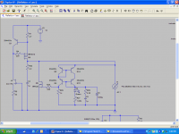
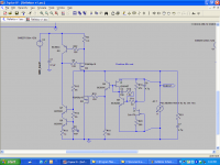
I have run simulations comparing Reflektor and V1.2. The V1.2 is at 60v out the Reflektor is at 10v out. The first image is the Reflecktor, the second the V1.2, the third is the AC analysis V(005) is the Reflektor, V(outpos1) is V1.2. Are my results correct (relatively speaking) ?
Thanks
Ken
I have run simulations comparing Reflektor and V1.2. The V1.2 is at 60v out the Reflektor is at 10v out. The first image is the Reflecktor, the second the V1.2, the third is the AC analysis V(005) is the Reflektor, V(outpos1) is V1.2. Are my results correct (relatively speaking) ?
Thanks
Ken
Attachments
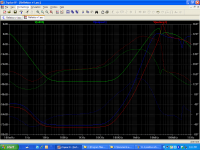
What are the solid lines ?
What are the dotted lines ?
They are output impedance traces versus frequency. Dotted is their phase. You can read the one I posted before in dB, also in Ohm as such (~7mOhm flat portion):
Attachments
They are output impedance traces versus frequency. Dotted is their phase. You can read the one I posted before in dB, also in Ohm as such (~7mOhm flat portion):
Salas, I know I've probably asked this before, so, forgive my poor memory... How do you get the impedance analysis? Which simulation CDM are you using? I understand how to make the formula in the graph output...
Ken
A correction is in order. My previous info was based on a friend´s measurements that is using my build.
I remade the measurements in real time and to reach 28Vout I need 10 minutes but with a different behaviour:
1st minute, Vout climbs steadily from 0 to 29Vout
9 minutes, Vout decreases slowly from 29 to 28 Vout
I remade the measurements in real time and to reach 28Vout I need 10 minutes but with a different behaviour:
1st minute, Vout climbs steadily from 0 to 29Vout
9 minutes, Vout decreases slowly from 29 to 28 Vout
Last edited:
Happy New Year Ricardo, just curious all Salas shunt regs sounds good with more current
P.S. Pics will welcome.
Happy New year for you too Merlin.
Yes... a little more current does wonders sometimes
")
- Status
- This old topic is closed. If you want to reopen this topic, contact a moderator using the "Report Post" button.
- Home
- Amplifiers
- Power Supplies
- The simplistic Salas low voltage shunt regulator