i can`t find 2.7C/WATT heatsink so i will the case as heatsink.
i think it will do the trick.
the case worked great as heatsink.
It buffers the termination not to change the OLG shape and bandwidth due to a shunting local decoupler, and that RC with just 100R does not drop too much itself. Lower value it starts interfacing too much.
Some dacs require 3.3V/30mA. In that case 100 ohms means dropping 3V or nearly 90%.
What about 47 ohm ?
What keeps from setting as much extra voltage initially as required to drop? If its a matter of using original transformers, then you don't do the RC filter buffering and the reg will just slow down on a heavy chip decoupling capacitor, rarely there will be functionality problems. At least we never heard any of the versions in this thread refusing a DAC or chip by oscillation. Still they did a decent job. Down to 10R RC its still working, you just lose some of the extra filtering benefit and just a little original spec, to answer your initial question.
the Cascode voltage, i.e. the Vgs of the outer device, should be at least 2times the Vp of the inside device.Remember, only the top one to change. It should be twice the Vgs spec of K170 at least and give higher free IDSS than the K170 under it so to best cascode.
A low Vp device for the inner Tr, allows a lower cascode voltage
What keeps from setting as much extra voltage initially as required to drop? If its a matter of using original transformers, then you don't do the RC filter buffering and the reg will just slow down on a heavy chip decoupling capacitor, rarely there will be functionality problems. At least we never heard any of the versions in this thread refusing a DAC or chip by oscillation. Still they did a decent job. Down to 10R RC its still working, you just lose some of the extra filtering benefit and just a little original spec, to answer your initial question.
My case (roughly): Xfrm 9VAC > 12 VDC > Pi filter drop 2 V = 10 VDC shunt input
Shunt reg v1.1 (BiB) set for 4 Vout > max R drop 0.6-0.7V@30 mA = R 20 ohm
Caps near IC: 680uF // 2.2uF
Is this acceptable?


I like that dude better while riding a lambretta.
But that is off topic
Same progress on Simplistic / Reflector
I had Simplistic running on 2 Lead acid cells for quite a few hours and now is time to recharge batteries so had a crack at the Reflektor.
It is all work in progress at the moment.
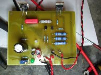
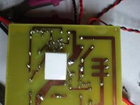
Top and botom of one Channel board
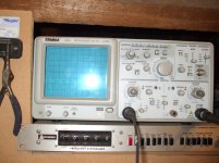
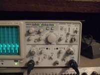
Fuzi picture using a 1.7V Green led signal at the output of reflektor with LM317 30 V preregulator.
Quite a bit of noise going trough (on crapyscope at 20 MhZ crapy scope is prety basic stuff but preaty standard even for poor man outside EU)
So best picture of what the scope alowd me to see.
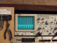
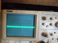
Much beter with 2V Red led.
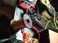
And the work around to stop noise from 317 going troug Just a coil of wire I had in the draw.
Sound wise arder of magnitude improvment between Green (wrong) LED and RED LED well worth spending same time finding the right one.
And no need to say the 317 plus choke even better.
Advantages of Reflektor
The Voltagge once dialed in and given few minutes for temperature to setle stay mor or less at the 24 V I have dialed in with the 100K pot in parralel to the 5.6 K resistor.
Changing the voltagge output of the LM317 from 32 to 25 Volts does very litle to the voltagge output.
I will eventualy go back to the Batteries for those (2 X12 Volts in series)
Voltagge will be between 27V (fully charged) and 24V dead batery.
To have sometink to keep a costant voltagge output inrespective of V in IMO is well worth this effort.
Reflektor is there to stay for a long long time.
Noise there is most definetley from bolted on 317
Yes I would like to have a flat line at the output and Choke as is made big improvment battery shuld be a bit better but still not a flat line as even LAC have Jhonson noise.
Question TIME
Did you notice similar noise at output of LM317?
Work arounds?
But that is off topic
Same progress on Simplistic / Reflector
I had Simplistic running on 2 Lead acid cells for quite a few hours and now is time to recharge batteries so had a crack at the Reflektor.
It is all work in progress at the moment.
Top and botom of one Channel board
Fuzi picture using a 1.7V Green led signal at the output of reflektor with LM317 30 V preregulator.
Quite a bit of noise going trough (on crapyscope at 20 MhZ crapy scope is prety basic stuff but preaty standard even for poor man outside EU)
So best picture of what the scope alowd me to see.
Much beter with 2V Red led.
And the work around to stop noise from 317 going troug Just a coil of wire I had in the draw.
Sound wise arder of magnitude improvment between Green (wrong) LED and RED LED well worth spending same time finding the right one.
And no need to say the 317 plus choke even better.
Advantages of Reflektor
The Voltagge once dialed in and given few minutes for temperature to setle stay mor or less at the 24 V I have dialed in with the 100K pot in parralel to the 5.6 K resistor.
Changing the voltagge output of the LM317 from 32 to 25 Volts does very litle to the voltagge output.
I will eventualy go back to the Batteries for those (2 X12 Volts in series)
Voltagge will be between 27V (fully charged) and 24V dead batery.
To have sometink to keep a costant voltagge output inrespective of V in IMO is well worth this effort.
Reflektor is there to stay for a long long time.
Noise there is most definetley from bolted on 317
Yes I would like to have a flat line at the output and Choke as is made big improvment battery shuld be a bit better but still not a flat line as even LAC have Jhonson noise.
Question TIME
Did you notice similar noise at output of LM317?
Work arounds?
Attachments
Yess of course is the pre regs. at least I think so as Coke is before input to RefleKtor but then again maybe source resistors to far or wrong (long track) somewhere.
LM 317 is point to point as was desperate to get sometink working.
I will not need it as LEAD ACID CELLS but if one is desperate (batery need charging)
a 317 with a coke can do...
Last I heard was question about Do Russians lowe their childrens Like we do
has it done any worthy thing since?
LM 317 is point to point as was desperate to get sometink working.
I will not need it as LEAD ACID CELLS but if one is desperate (batery need charging)
a 317 with a coke can do...
Last I heard was question about Do Russians lowe their childrens Like we do
has it done any worthy thing since?
Those wavy screens are oscillation. Voltage at reg's out should have small drift and when viewed on scope's AC mode at 5mV/div be close to what it gives when set to GND. How high raw DC you can feed from a bridge rectifier and capacitor filter to the reg's input, straight without a chip? If its 30V at least you are OK for 24V output. Try that first, maybe there is bad interaction between 317 and reg's input CCS.
Hi, here's the schematic I use for heating direct heated triode filaments. It works very stable at 1A and more, output ripple is in mV range. You can use my layout or make your own, raster is 2.54mm. Make sure you use thick conductors if currents are exceeding 250mA.
Thanks Nick, it's a good job you did on this one!
I am thinking of using this board for the filament of my VT-25 (7.5V at 1.5A) and my VT-25A (7.0V at 1.2A)....do I use R1 = 0.44R and 0.55R; then adjust to 7.5V or 7.0V with the trimmer??
Any other part changes needed??
Cannot buy 2sk170 nor esk117 here....what else can I use??
Thankyou....
Ask to spencer the Toshiba SK170BL http://www.diyaudio.com/forums/swap-meet/131284-toshiba-2sk170bl-sales.html
About SK117 ask Tea-Bag GB BiB http://www.diyaudio.com/forums/group-buys/188974-gb-thread-salas-ssr1-1-bib-shunt-reg.html
About SK117 ask Tea-Bag GB BiB http://www.diyaudio.com/forums/group-buys/188974-gb-thread-salas-ssr1-1-bib-shunt-reg.html
hi guys
sorry about my ignorant. i am building this simplistic salas. i am wondering whats the smallest cap value can i put on the output of the salas reg? as the supplied circuit already has 200uf at the input.
would 10uf MKP or tantalum enough?
thanks in advance
erwin
sorry about my ignorant. i am building this simplistic salas. i am wondering whats the smallest cap value can i put on the output of the salas reg? as the supplied circuit already has 200uf at the input.
would 10uf MKP or tantalum enough?
thanks in advance
erwin
- Status
- This old topic is closed. If you want to reopen this topic, contact a moderator using the "Report Post" button.
- Home
- Amplifiers
- Power Supplies
- The simplistic Salas low voltage shunt regulator