Oh boy, I'd be very weary of oscillations. If anything, I'd have used the CCS from Salas' new circuit, and the shunt from me. p-channel mosfet in the CCS, n-channel in the shunt. Fast shunt, excellent CCS.
Which CCS you use, meaner V1.2 or V1.2, here is link http://www.diyaudio.com/forums/power-supplies/143693-simplistic-salas-low-voltage-shunt-regulator-190.html#post2103465
What I was saying is that if I were you, I would use the CCS from Salas v1.2, and the shunt from my 5k. It simulates well, but I haven't built it.
I'am glad to hear you again. Please let us know the scehmatic of your 5k shunt, better if you can draw full schematic togheter Salas V1.2
") & handfull how can reach several voltages
& handfull how can reach several voltages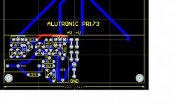
First to make 2 regs. more for balanced Salas NJFET RIAA I want to try only with 2 regs like this schematic:
It's OK?
An externally hosted image should be here but it was not working when we last tested it.
It's OK?
I can try & report. Thank you. I see this pic Walter Jung regs
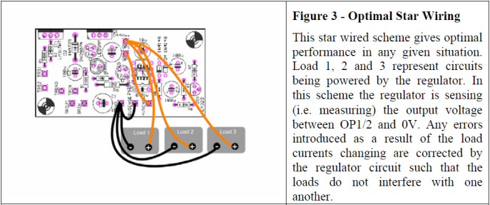
"Optimal Star Wiring
This star wired scheme gives optimal performance in any given situation. Load 1, 2 and 3 represent circuits being powered by the regulator. In this scheme the regulator is sensing (i.e. measuring) the output voltage between OP1/2 and 0V. Any errors introduced as a result of the load currents changing are corrected by the regulator circuit such that the loads do not interfere with one another."
An externally hosted image should be here but it was not working when we last tested it.
"Optimal Star Wiring
This star wired scheme gives optimal performance in any given situation. Load 1, 2 and 3 represent circuits being powered by the regulator. In this scheme the regulator is sensing (i.e. measuring) the output voltage between OP1/2 and 0V. Any errors introduced as a result of the load currents changing are corrected by the regulator circuit such that the loads do not interfere with one another."
Last edited:
Picture above is from ALWSR regulator manuals. ALWSR is series regulator (based on Walt Jung topology) and Simplistic Salas is shunt regulator.
Shunt regulators can somethimes go into oscillations with multiple loads and wires with different lenght and multiple capacitors on load.
You can isolate loads from each other, but you will throw away all benefits of shunt
(low output Z and good regulation). Just be careful and check everything with scope if regulator is stable.Attachments

Last edited:
Picture above is from ALWSR regulator manuals. ALWSR is series regulator (based on Walt Jung topology) and Simplistic Salas is shunt regulator.
Shunt regulators can somethimes go into oscillations with multiple loads and wires with different lenght and multiple capacitors on load.
You can isolate loads from each other, but you will throw away all benefits of shunt
Thanks for the input I didn't see Walts are series regulator. Salas is using 1 reg for 2 loads (Stereo Salas Simplisticis NJFET RIAA)....
merlin el mago said:Thanks for the input I didn't see Walts are series regulator.
Awesome life work, The Holly Bible for regulators: CLICK
A MUST to read if you are playing with regulators and power supplys.
What I was saying is that if I were you, I would use the CCS from Salas v1.2, and the shunt from my 5k. It simulates well, but I haven't built it.
I'am glad to hear you again. Please let us know the schematic of your 5k shunt, better if you can draw full schematic togheter the CCS Salas V1.2 & handfull how we can reach several voltages?
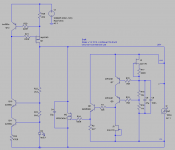
Sorry, I wasn't paying attention to this thread. Here's a draft of what I had in mind. As far as I know it has never been built, so take it with a grain of salt. The usual issues should apply, good layout, etc. It simulates well.
Thanks for answer, how can do to get differents voltages, for example +45Vout, +-24Vout, +-5Vout, etc?
post2996,
I note that C4 is shown, as with all decoupling capacitors, at the transistor that changes current demand quickly to try to compensate for the current demands of the load.
This is where I have been placing it. But many are locating the decoupling at the load.
Can the location actually affect stability.
Is there a way to simulate the trace capacitances and inductances to show if location can produce different performance.
Hi Andrew
I have been experimenting with this output cap placement and can assure you that the location really affects stability.
In some cases, the shunt stuck on 13v. To get to the desired vout (37v) I needed to shut the power off for some seconds (3~5) and than power on again.
With a carefully chosen GND layout, the problem is now solved.
(Thanks Salas)
I have been experimenting with this output cap placement and can assure you that the location really affects stability.
In some cases, the shunt stuck on 13v. To get to the desired vout (37v) I needed to shut the power off for some seconds (3~5) and than power on again.
With a carefully chosen GND layout, the problem is now solved.
(Thanks Salas
)Thanks for answer, how can do to get differents voltages, for example +45Vout, +-24Vout, +-5Vout, etc?
For smaller voltage output decrease the value of R18 and R16. The current limit is set by R25. To get 45V output Q8 would have to be replaced with some higher voltage npn.
- Status
- This old topic is closed. If you want to reopen this topic, contact a moderator using the "Report Post" button.
- Home
- Amplifiers
- Power Supplies
- The simplistic Salas low voltage shunt regulator