This thing again..
What do you mean by best quality? Low ESR? Any recommendations? Do I skip all 0.1uF bypasses?
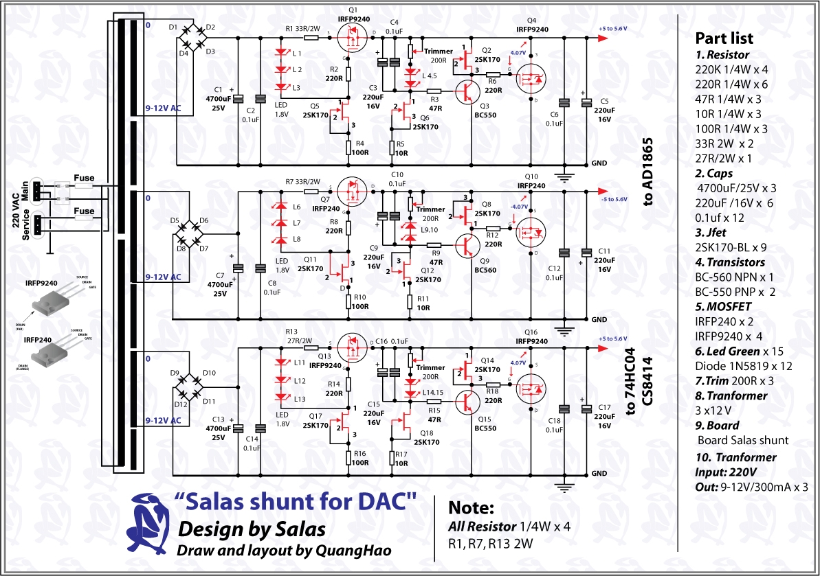
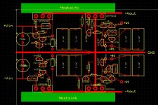
Thanks, I will try those. Has those C1/C7/C13 too big value (4700uF) after thc FWBRs?
...best quality capacitors across Vrefs and lose the 0.1uF bypasses, its a hit or miss.
What do you mean by best quality? Low ESR? Any recommendations? Do I skip all 0.1uF bypasses?
Four 31dq05 Schottky diodes for your fwbr.
Thanks, I will try those. Has those C1/C7/C13 too big value (4700uF) after thc FWBRs?
BG red NP if you can find. Yes, I would not care about bypasses, sometimes they don't marry well. Since there are positions for them bcs you are having a board, you could make a subjective comparison with and without given your particular main caps and bypasses I guess. Start without, and after you got a good grip of the performance add them and decide.
It will work with a range of values Cfilter, the CCS rejects a lot of ripple. But those people made it and listened to it that way. Its blended with their DAC, better do what they did and then you may play IMHO.
It will work with a range of values Cfilter, the CCS rejects a lot of ripple. But those people made it and listened to it that way. Its blended with their DAC, better do what they did and then you may play IMHO.
Hypnotize shunt ?
What are you using it for ?
I pre-ordered one Buffalo 32 DAC & one Ivy I/V, surely I will use a R-Core Tx from France to supply the Hypnotize shunt for the DAC.
Quick questions. I read the thread (Beast!) and am interested in doing a V1.1 shunt for a B1.
Question: whats the recommended voltage drop vs the raw supply?
I note that the simulations are all about 6V.
Also, I found a switching supply TDK LS25-24.
The Data sheets for it are LS Series
http://www.us.tdk-lambda.com/lp/ftp/manuals/ls_manual.pdf
Would this work?
Any down side other than perhaps extra switching noise?
Thanks in advance.
Doug
By the way I used my Blog to mark posts in this thread.
http://www.diyaudio.com/forums/blogs/dougl/195-power-supplies-b1.html
You need a single polarity 18V reg in other words? 6-10V Vin-Vout will do. Prefer 10V if you have it.
You mentioned 1.1. Are you looking for performance beyond V1's standard?
There is 1.2 in the beta. Works fine as by now. 1.1 was just a buffer test that led to 1.2's development.
It can work without oscillation if the local B1 big electrolytic cap has enough ESR, or if it isn't there at all. In any case this reg performance class needs careful application and termination, checks with scope, coaxial shielded remote sensing wire. If you are interested I can release what is on beta now for you, but it has not been deployed widely yet, its speedier, can not guarantee zero hassle to each different use, V1.0 has been used by hundreds of people on almost anything and its the surely deaf one to adverse application.
I was looking at the V1 with the LED string on the CSS. Example Post 1084 http://www.diyaudio.com/forums/powe...-voltage-shunt-regulator-109.html#post1928046
Honestly I was looking for something simpler than V1 and read the thread to understand the issues involved. The engineering seems so good it looks like building it as a reference is my best option. For my needs the performance seems fine and stability will be welcome.
I will omit both electrolytes and the 1 ohm on the B1.
Thanks.
Doug
That one with layout drawn by Disco is fine for you then. Just use a 18V Zener, or follow my recommendation for a 8-9xLed string around 2Vf each, cathodes facing down. Maybe on a vertical sub board. Does better. In any case up the Vref bypass cap to 1000uF. 26-28Vin.
Regards
Regards
Perfect.That one with layout drawn by Disco is fine for you then.
Thank you.
Doug
V1.2
One single rail schematic for up to 60V DC out. Two symmetric schematics for up to +/-22V DC out. 6-10V DCin-DCout is enough. 28V Max in for the symmetric. All tried and tested. Two beta tests. The single in Athens, the symmetric in Sydney. Performance seems adequate.
One single rail schematic for up to 60V DC out. Two symmetric schematics for up to +/-22V DC out. 6-10V DCin-DCout is enough. 28V Max in for the symmetric. All tried and tested. Two beta tests. The single in Athens, the symmetric in Sydney. Performance seems adequate.
Attachments
Both the noted TO-247 and TO-220 Mosfets can work on all schematics. Both types tested. 2N5457, BF245A for Q6 exchangeable. 2SK170 Q6 for the lower voltage range symmetric also. Up to 10uF MKT or MKP for C2. 47uF if with chemical cap. Output RC Zobel values are standard. Film cap there.
Attachments

Big news then!
That "TO-240" is most probably a typo for TO-247.....
I do hope IRFP9140 will work well in the 1st schematic (Single rail up to 60V DC out) or do you prefer TO-220 now?
Output C3 preferably MKP, isn't it?
While C2 can be also a premium elcap (i.e. Silmic II), according to the polarity sign.
I like your assessment about performance....like a Rolls Royce engine.....hp: adequate!
Yes typo, I changed it now, thanks.
IRFP9240 or 9140 OK. No I don't prefer them TO-220s, I just tried to see if there will be problems or not because I had some. Heat is high on the single above 40V on my sink, I would rely more on TO-247. The 9610 gives more PSRR higher band in sim, but the performance threshold is excellent already with IRFPs. Another two singles have been made for beta with the heavier Mosfets by a friend here.
47uF the most if you will use a lytic for bypassing the Vref as I mentioned, but an MKT or MKP is advised. The testers will surely have to say more on such.
Output C3 must be film, MKT or MKP. Or 22-47uF medium ESR lytic instead of the RC across out. 2N5459 in CCS tail 7mA Idss.
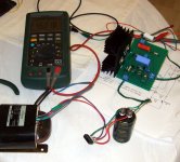
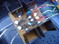
Here's Bill's layout BTW. He uses low value Vref caps now because he has it on the higher portion of his active system after he tested with lytics also. No less than 4u7 C2 for a full range application, preferably 10uF. I used a Philips MKT 10uF which was relatively compact and bypassed with a Vishay MKP1837 in that photo for example.
IRFP9240 or 9140 OK. No I don't prefer them TO-220s, I just tried to see if there will be problems or not because I had some. Heat is high on the single above 40V on my sink, I would rely more on TO-247. The 9610 gives more PSRR higher band in sim, but the performance threshold is excellent already with IRFPs. Another two singles have been made for beta with the heavier Mosfets by a friend here.
47uF the most if you will use a lytic for bypassing the Vref as I mentioned, but an MKT or MKP is advised. The testers will surely have to say more on such.
Output C3 must be film, MKT or MKP. Or 22-47uF medium ESR lytic instead of the RC across out. 2N5459 in CCS tail 7mA Idss.
Here's Bill's layout BTW. He uses low value Vref caps now because he has it on the higher portion of his active system after he tested with lytics also. No less than 4u7 C2 for a full range application, preferably 10uF. I used a Philips MKT 10uF which was relatively compact and bypassed with a Vishay MKP1837 in that photo for example.
Attachments
Salas,
Can you comment a bit about the design choices?
The differences I see are:
In the series section, PNP replaces 3 LED reference
In series section, Cascade or Ring of 2 NPN replace 2SK170 jfet css
In Shunt section, Resistor replaces Zener String
In Shunt section, added RC feedback on Ref driver.
IN shunt section, added NPN follower.
In shunt section, added remote sense "requirement"
This is in contrast to Post 501.
Just Curious of your perceived merits of the changes?
Doug
Its about the performance things discussed in this thread.
The cascode tail increases the psrr of the ccs. Vbe ref for no Rset hassle with LEDs. Cascoding brings it up to par.
The resistor comes handy for an adjustable output. Its low noise enough but leds are better, and stiffer for drift btw.
The RC feedback is a compensation to keep oscillations away.
The buffer helps open up Zo performance in frequency.
Rsensing is a good practise not to throw the better performance measures out of the window.
About subjective merits, I hand it over to the testers.
- Status
- This old topic is closed. If you want to reopen this topic, contact a moderator using the "Report Post" button.
- Home
- Amplifiers
- Power Supplies
- The simplistic Salas low voltage shunt regulator