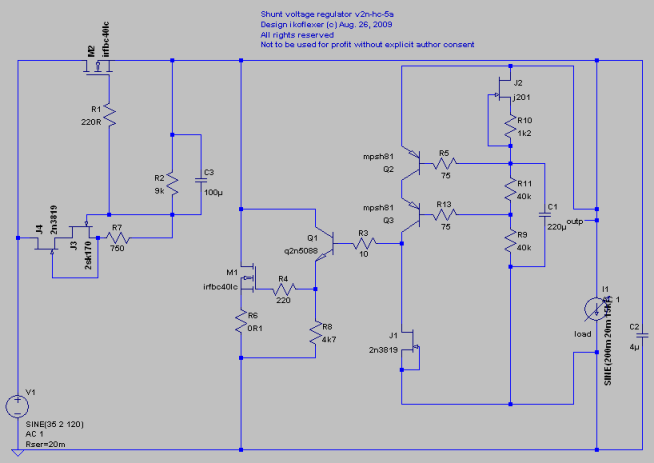
Ikoflexer,
The Farnell parts from the U.S. have just arrived. So as soon as the 2sk170 from HongKong arrives I can spend a day to build v2.
Can I apply the same to v2? I mean adding some resistance between g and s of the Vref NJFECT, and use a film cap there.
I've tested something like this.
This one should be technically superior hands down. Interesting to know how it will be perceived for tone. HiFiNutNut is doing much interesting evaluation work in a really big system. Fortunate that is.
Who knows, so many times all those performance numbers mean nothing and the sound is bad. HiFiNutNut may tell us soon. Luckily, we have established v1 and v1.1 to go back to!
Thanks Ikoflexer and Salas.
I have just finished work and am heading home now (no work assignments now thanks to the economic crisis so I do anything I want just stay in the office for 7-8 hours). It has been nice chatting with you guys today. Will chat tonight or tomorrow.
Regards,
Bill
I have just finished work and am heading home now (no work assignments now thanks to the economic crisis so I do anything I want just stay in the office for 7-8 hours). It has been nice chatting with you guys today. Will chat tonight or tomorrow.
Regards,
Bill
Everytime the performance is better by 6dB in audio, in any aspect, I can feel the signal coming better to the fore. I tend to think that it is not about bettering the actually non perceivable thresholds under a more than enough point, but the real meaning is that overal linearilty is bettered. So for all things equal I expect V2 to rightfully shine in a very demanding system. Interesting procedure non the less.
Just before I go, Iko, could you please simulate with that bypass capacitor 1uF instead of 220uF? You don't need such a big cap for 80k.
As I said before, the values of all passive parts are yours to tweak.
I've simulated a small cap there, and also tested (measured) the noise. About this cap, I think you should trust your ears more.
Goodnight guys.

Cheers! It's hard to find an adequate response for you salas, you NEVER sleep!
And it was more. Analogue dither.I've simulated a small cap there, and also tested (measured) the noise.
Cheers! It's hard to find an adequate response for you salas, you NEVER sleep!
NY of a guy?
substitute 5.2mA for the current through the jFET.In my working example, Idss=7.3mA, so 0.6 + 0.0073 * (2200 + 200) = 18.12 (V). I only got 13V.
Now have a think about why only 5.2mA rather than 7.3mA is flowing through the jFET.
It is down to junction temperature (Tj) and voltage across the device (Vds).
Neither of the specification values apply to the operational conditions in the circuit.
Just to let you know guys, for better focus and to expand on certain aspects I opened a new thread for v2 and beyond.
http://www.diyaudio.com/forums/power-supplies/153715-my-take-discrete-shunt-voltage-regulator.html
http://www.diyaudio.com/forums/power-supplies/153715-my-take-discrete-shunt-voltage-regulator.html
I did some work in the past week and am happy to share what I have learnt.
In terms of tunning, other than an optimal PCB layout, there are only two things we could do - (1) The capacitor in the Vref; and (2) the output capacitor.
I initially built it with a 100uF electrolytic capacitor in parallel to a 1.1uF film capacitor and in parallel to a ?k (low k) resistor. I reported that the sound was very good but I was not comfortable with the bypass cap and there were areas improvements could be made.
There was a bit uneasiness in the sound and I suspected that it was due to shunting the electrolytic cap 100uF witha 1.1uF film cap. The tests proved that I was right on this one.
First I removed the caps and put in a 470uF 25V Rubycon ZL.
No, I didn't like the sound. The sound stage was solid but artificially too big and thick. The electrolytic capacitor simply slowed down the music and cut out the fast transients. The fine resolution with a good film capacitor was gone. The vibros of the string instruments were gone. It became typical HiFi. No problem with Rock / Pop music. But not suitable for fine classical music. I would prefer the other shunt regulator or the ALW Jung Regulator I had on hands.
Next, I removed the electrolytic capacitor and put in the 1.1uF capacitor only. Now the details, resolution, air came back, and gone were the unnaturalness of the 100uF||1.1uF. It was much much better. Due to the relative small value of the capacitor comparing to the resistor, low frequency response suffered a bit.
About the film capacitor. Film capacitors make a lot less difference comparing to electrolytic capacitors, but the difference is still there. They are much better than electrolytic capacitors, for sure.
Here is an untold secret: I have compared quite many capacitors. For polypropylene capacitors many people look for them based on recommendations and they select from the best brands. But these are usually high voltage caps designed for passive crossovers. They are bulky and usually very expensive.
For line level circuits, I found the Vishay / BC Components "blue box" polypropylene capacitors (series: MKP 416 to 420) to be the most neutral sounding, equals and outperforms all other capacitors I have had tried. Note that they are designed for high frequency and high stability applications. They are cheap. I like the 63VDC versions because they are relatively small. The largest value is 1.2uF but they were sold out. About 6 months ago, I bought 2 dozens of 1.1uF from Digi-key for spare parts. I am going to use it to replace the ICW SA Clarity Cap at the output of my SACD player. That is how good the capacitor is.
Since I built the v1 plus the resistor and buffer mod, there have been a number of posts hinting the way to increase the Vref resistor in order to use a film capacitor. Ikoflexer suggested using a resistor between the g and s of the 2sk170. What gave me the insurance was that it was suggested 200uA was fine. So I gathered anything between 200uA to 8mA would work. This is a very large range and gives us the flexibility.
I replaced the two 2sK170s because I suspected one of them might contribute to the large voltage shifting after turn on. After the replacement, both rail voltages shifted (to higher this time instead of one of them much lowered), but the voltage shifting became smaller. I have not noted down how much.
I spent no less than 6 hours playing with the Vref an eventually got it right. Things were never as easy and as straight forward as they seemed.
Once a solution is worked out, it became very easy though. And here it is:
Don't be bothered with the Rtrim. There is no point of adjusting the resistor to come to the right voltage. I would prefer using a fixed resistor (e.g. 27k) with a fixed capacitor (1.1uF) so that the corner frequency can be predetermined and not affected. Installed a 2k trimpot between the gate and source of the 2sk170. This allowed easy tuning to the desired voltage. After that, I replaced the trimpot using the closest value of 560R. This provided about +13.6V and -13.4V, which was good enough.
The low frequency response no longer suffered.
Below is the updated PcB layout I used.
An externally hosted image should be here but it was not working when we last tested it.
Last edited:
Now the output capacitor. Here it can only be an electrolytic capacitor. It makes far less difference comparing to the capacitor at the Vref.
I tried 47uF, 100uF and 470uF Rubycon ZL. When the 470uF Rubycon ZL (ESR is about 0.038R) was installed, the circuit oscillated. Even without a signal, I could hear some very high frequency coming out from the tweeter. Since it was low volume, I asked my wife to listen to it and she confirmed that she could hear it clearly even standing at the door of the room.
So the regulator does not like low ESR capacitor, same as any other regulators.
I replaced it with a general purpose, garden variety Xicon 100uF/50v, the high frequency ringing was no longer audible. The music became clearer.
I have no intention to give any more information on this, because the output capacitor may be load dependant as well. What suits me may not suit you, and we all have our own preferance to different colourations.
Last edited:
I have learnt quite a bit through this exercise. Here is an important finding that I am happy to share. Of course, many of you would have learnt this long time ago.
The opa627 buffer is not my permanent preamp. It is used for testing regulators only. I will also use it for speaker measurements.
I deliberately made the wiring to the PSU a bit longer using only 22aug wires. It was about 15cm long, slightly curved, which had about 0.008R resistance and perhaps 90nH inductance. Because I thought in my real active XO/EQ board I could never manage to have wires less than this distance for all of the opamps. So catering for a worse case scenario and taking the average scenario would be a good idea to ensure the final circuit works.
I took a significant amount of efforts to find out how I can make the sound cleaner.
When I replaced a 12cm session of the 22aug wire with 15A rated electrical cable, the sound became a lot cleaner. Sound stage, air, transient attack became so much better. The improvement was even greater than changing a regulator! I am not exaggerating.
From this I found that these opamps, without local bypass, really require a very low impedance at high frequencies to work properly. I read this out of dozens of articles for as long as a few years now, but this time I REALISED it in my own experiments.
- Status
- This old topic is closed. If you want to reopen this topic, contact a moderator using the "Report Post" button.
- Home
- Amplifiers
- Power Supplies
- The simplistic Salas low voltage shunt regulator