Its a system thing. If you drive 100k line input, 1uF is OK. If you drive 50k, 2u2 is OK. 3u3 will do well in to 20k. There is a below arm-cart resonance roll off rate that I want to preserve in combination with the interstage coupling. Very low coupling just promotes mechanical feedback if you have large speakers.
remote sensing is the equivalent to extending the PCB all the way to the amplifier.
What have we been saying about instability and it's possible causes?
Did PCB layout get suggested as a possible cause of instability?
Now if we all use remote sensing, what proportion of us are going to come back and say "my SQ has gone all screechy" or "the treble has been exaggerated" or "I'm hearing a lot of sibilance that wasn't there before".
Keep the sensing on board.
Keep the output VERY CLOSE to the amplifier power input. B
A back to back pair of PCBs with a 2mm links soldered between the respective holes.
If you can guarantee that all remote sensing implementations will have no stability concerns then go ahead.
Doing other wise will seriously jeopardise the regulator/amplifier performance.
I don't think I can guarantee any stability with remote sensing or otherwise. To be safe, it's best to have the regulator as close to the load as possible, and connected with thick wire. Do your best to minimize the resistance between Out and Load.
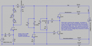
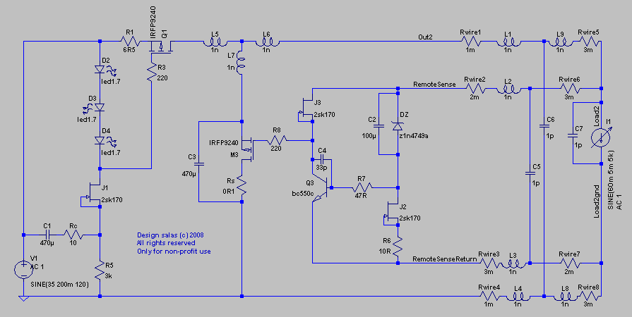
So, for now, maybe we should ignore all the remote sensing stuff. For those that really want to risk or for some reason have no option but leave some distance between the regulator and load, would anyone be interested in exploring the issue? Any expert opinions on the attached circuit? Note that I don't have much experience with this remote sensing stuff.
So, for now, maybe we should ignore all the remote sensing stuff. For those that really want to risk or for some reason have no option but leave some distance between the regulator and load, would anyone be interested in exploring the issue? Any expert opinions on the attached circuit? Note that I don't have much experience with this remote sensing stuff.
Attachments
Hi Iko,
start by adding various combinations of inductance and capacitance to your sense leads, then simulate.
These reactances will have a lot more effect than a couple of milliohms of resistance in either or both of the sense leads.
BTW,
the Dz to R6 route is part of the sense lead circuit.
The circuit is a measuring bridge. The top and bottom of the bridge must tap into the sense leads and these sense leads must go to the sense locations.
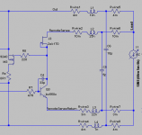
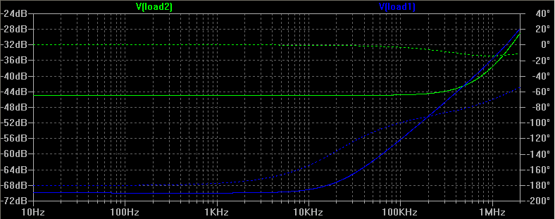
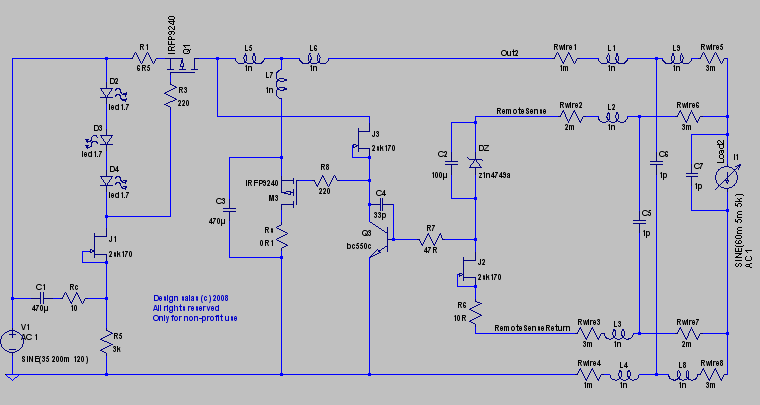
Andrew, thanks! See attached. Do you think it's sloppy enough to resemble a careless implementation? I'm trying to deliberately do this so we can look not at best case scenarios first. Feel free to suggest different parts values possible closer to reality. The attached circuit is both stable and with performance as good as without all the sensing stuff. In simulation, of course.
BTW, initially I have tried to include the DZ-J2-R6 block in the sense circuit but lost 20dB in output impedance. I don't have an explanation for that.
BTW, initially I have tried to include the DZ-J2-R6 block in the sense circuit but lost 20dB in output impedance. I don't have an explanation for that.
Attachments
connect the extra side of the measuring bridge and then reduce the parasitics to almost zero. The performance should then come back.
If the parasitics are reduced to zero the performance should be identical.
Add some inductance between the CCS and the main shunt element, both +ve and -ve legs.
Add inductance to every wire connection.
Add some capacitance across the load.
Add some capacitance between parts that are very close together.
Set all the capacitances and inductances initially to 1pF and 1nH.
Hi Ikoflexer,
I'm following this thread with interest. It's wonderful to see your relentless efforts unfold over the last weeks to create the ultimate regulator.
Regarding the remote sensing, I'm surprised by your implementation.
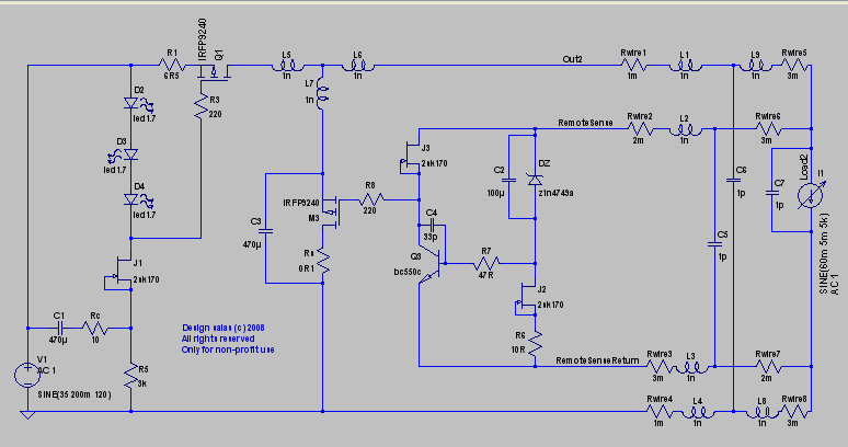
Basically this regulator is a constant current source from the raw supply to the load, with a shunt in parallel.
The high output impedance current source is converted into a low output impedance voltage source, by shunting the excess current with Q4.
To do so, Q4 is part of a feedback loop.
Zener ZT and Q3's Vbe form the sense part. Any excess voltage on the regulator output is converted (after ZT's levelshift) into a correction current by Q3.
This error current charges/discharges the gate of Q4, thus correcting towards the desired output voltage.
J3 is merely a bias current source.
So I would expect that you place ZT and Q3 as remote sensor close to the part in the load where you want to achieve constant voltage.
Then Q3's error current is passed back over to the shunt regulator, to the gate of Q4.
All components stay in the regulator, only ZT and Q3 move over to "the other side".
This arrangement should keep the load voltage constant.
Of course you need to watch for instability, particularly with the parasitic components as suggested by AndrewT.
Your quest for perfection is starting to conflict with the 'modular' approach.
This seems to be a fact of life ;-) Whenever something needs to be modular and/or universal, you need to compromise...
Ultimately every stage in Salas's RIAA amplifier should have its own, local regulator.
No remote sense, just local implementation, where a dedicated regulator keeps the voltage on the 1st amplifier stage constant and another dedicated regulator takes care of the 2nd amplifier stage.
I don't think you can do better than that, but it isn't modular and universal anymore, alas...
Keep up the good work and "never stop exploring".
I'm following this thread with interest. It's wonderful to see your relentless efforts unfold over the last weeks to create the ultimate regulator.
Regarding the remote sensing, I'm surprised by your implementation.
Basically this regulator is a constant current source from the raw supply to the load, with a shunt in parallel.
The high output impedance current source is converted into a low output impedance voltage source, by shunting the excess current with Q4.
To do so, Q4 is part of a feedback loop.
Zener ZT and Q3's Vbe form the sense part. Any excess voltage on the regulator output is converted (after ZT's levelshift) into a correction current by Q3.
This error current charges/discharges the gate of Q4, thus correcting towards the desired output voltage.
J3 is merely a bias current source.
So I would expect that you place ZT and Q3 as remote sensor close to the part in the load where you want to achieve constant voltage.
Then Q3's error current is passed back over to the shunt regulator, to the gate of Q4.
All components stay in the regulator, only ZT and Q3 move over to "the other side".
This arrangement should keep the load voltage constant.
Of course you need to watch for instability, particularly with the parasitic components as suggested by AndrewT.
Your quest for perfection is starting to conflict with the 'modular' approach.
This seems to be a fact of life ;-) Whenever something needs to be modular and/or universal, you need to compromise...
Ultimately every stage in Salas's RIAA amplifier should have its own, local regulator.
No remote sense, just local implementation, where a dedicated regulator keeps the voltage on the 1st amplifier stage constant and another dedicated regulator takes care of the 2nd amplifier stage.
I don't think you can do better than that, but it isn't modular and universal anymore, alas...
Keep up the good work and "never stop exploring".
Hi Ikoflexer,
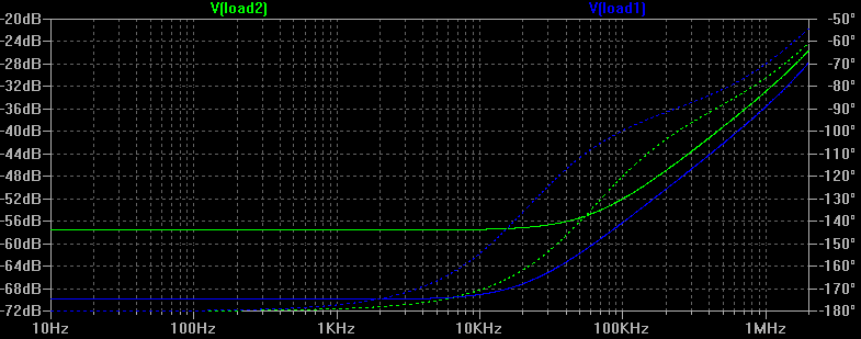
please be careful now with the voltages you measure. What's the reference now?
V(load1) and V(load2) are referring to which node in the schematic?
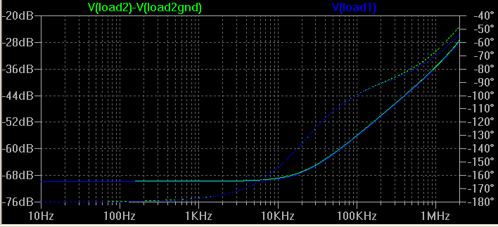
It would be better to probe V(load1)-V(load1_ground_reference), so a differential voltage.
same for V(load2)-V(load2_ground_reference).
Remember the purpose of the shunt regulator is to keep the voltage across the load constant!
We don't care about the 'system ground' node, just the local ground node of the 'circuit under test'.
Can you please indicate the important node pair in your schematic(s).
Further I think your initial parasitic inductances where more realistic. 1nH/mm as a rule of thumb for wire inductance defies the idea of 'remote sensing' ;-)
please be careful now with the voltages you measure. What's the reference now?
V(load1) and V(load2) are referring to which node in the schematic?
It would be better to probe V(load1)-V(load1_ground_reference), so a differential voltage.
same for V(load2)-V(load2_ground_reference).
Remember the purpose of the shunt regulator is to keep the voltage across the load constant!
We don't care about the 'system ground' node, just the local ground node of the 'circuit under test'.
Can you please indicate the important node pair in your schematic(s).
Further I think your initial parasitic inductances where more realistic. 1nH/mm as a rule of thumb for wire inductance defies the idea of 'remote sensing' ;-)
jeepee, it's nice that you decided to join the discussion. You're right on many counts. Indeed, I'm struggling here for weeks to get an improvement, something that would take an engineer a few hours. But it's fun for me, nonetheless.
In my opinion, for light loads, there is hardly any point in doing something else other than what we call v1, basically salas' initial schematic shown above. What I'm after is heavier loads, where a lower output impedance would make a real difference, and also a wider bandwidth (while nice, this is not so important for me). Each solder point is a potential resistance, and each piece of wire is too, forming a series of voltage dividers; that got me thinking that we're regulating the voltage at a point other than exactly where the load needs its voltage regulated. Perhaps it's not important, but then again, it's fun to explore this. One thing led to another and I arrived at the idea of remote sensing.
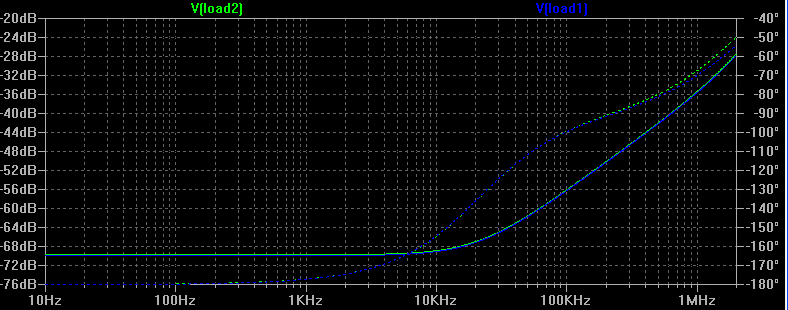
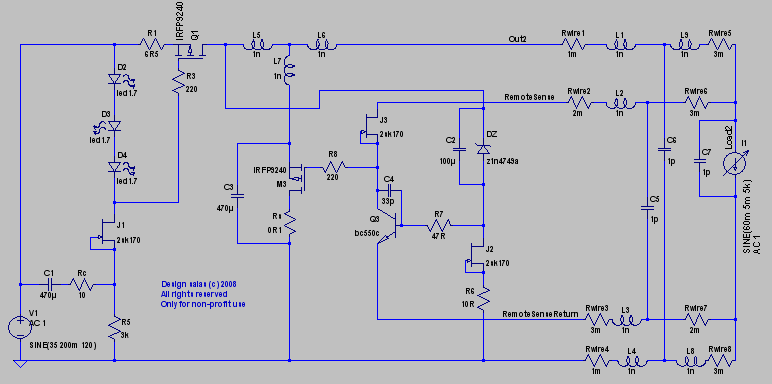
Thank you for reminding me that what we need is to maintain a constant voltage drop across the load. True, the plots above showed the voltage drop between the top of the load and main ground, which is not the same thing. I lost track of this point in the fever of trying all these things. Well, and now theory and simulation do agree. All sensing is remote in this next circuit, and look what it does.
BTW, regarding your thought that each stage should have its own regulator, I agree. In fact I've seen one commercial amp in which each stage had its own regulator; it makes sense. For light loads one can probably get away with one CCS and multiple shunts connected to it, but since this is a low parts count circuit, why not build an entire thing.
I will try to set the parasitics to values as close as possible to reality and redo all this; now everyone probably has their own ideas to what those values are, so do suggest some if you can think of anything.
Finally, I always do test for stability, after any changes.
In my opinion, for light loads, there is hardly any point in doing something else other than what we call v1, basically salas' initial schematic shown above. What I'm after is heavier loads, where a lower output impedance would make a real difference, and also a wider bandwidth (while nice, this is not so important for me). Each solder point is a potential resistance, and each piece of wire is too, forming a series of voltage dividers; that got me thinking that we're regulating the voltage at a point other than exactly where the load needs its voltage regulated. Perhaps it's not important, but then again, it's fun to explore this. One thing led to another and I arrived at the idea of remote sensing.
Thank you for reminding me that what we need is to maintain a constant voltage drop across the load. True, the plots above showed the voltage drop between the top of the load and main ground, which is not the same thing. I lost track of this point in the fever of trying all these things. Well, and now theory and simulation do agree. All sensing is remote in this next circuit, and look what it does.
BTW, regarding your thought that each stage should have its own regulator, I agree. In fact I've seen one commercial amp in which each stage had its own regulator; it makes sense. For light loads one can probably get away with one CCS and multiple shunts connected to it, but since this is a low parts count circuit, why not build an entire thing.
I will try to set the parasitics to values as close as possible to reality and redo all this; now everyone probably has their own ideas to what those values are, so do suggest some if you can think of anything.
Finally, I always do test for stability, after any changes.


- Status
- This old topic is closed. If you want to reopen this topic, contact a moderator using the "Report Post" button.
- Home
- Amplifiers
- Power Supplies
- The simplistic Salas low voltage shunt regulator