Have they (others and syn08) discussed the changes when sense is routed this way?
BTW, I made a mistake above, saying that 20cm of cable would be 2mOhms, when it is actually 4mOhms.
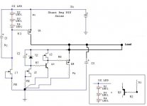
Here is the output impedance of v1 as I always simulate it, without a resistance between OUT and Load.
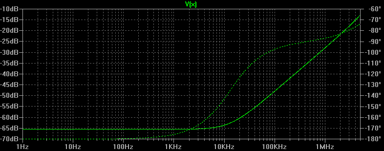
A resistance of 5 milliohms, sense components connected as usually shown in the schematic.
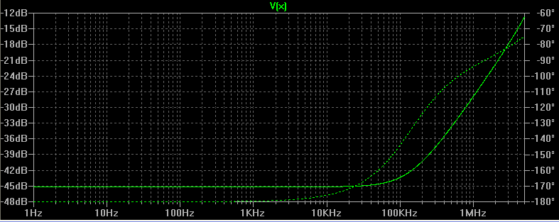
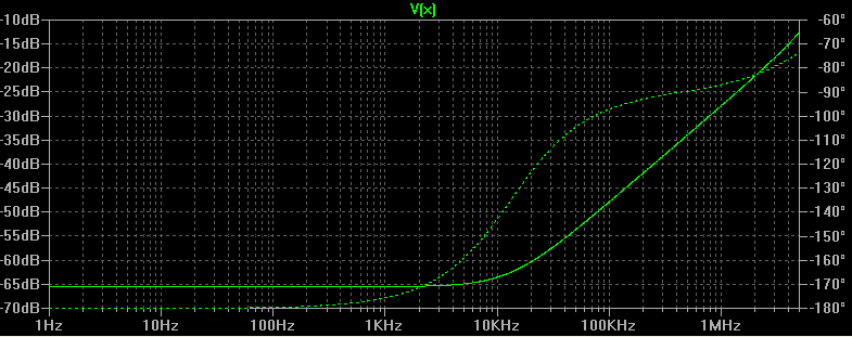
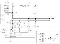
And sense components connected directly to the load.
I think people in general may not realize what a big difference this can make. I didn't until I actually simulated it.
BTW, I made a mistake above, saying that 20cm of cable would be 2mOhms, when it is actually 4mOhms.
Here is the output impedance of v1 as I always simulate it, without a resistance between OUT and Load.
A resistance of 5 milliohms, sense components connected as usually shown in the schematic.
And sense components connected directly to the load.
I think people in general may not realize what a big difference this can make. I didn't until I actually simulated it.
Perfect! Thanks. The simulation shows that output impedance is almost not affected at all even by quite a resistance between OUT and LOAD, where as before even 200uOhms would have an effect.
In theory I knew that sense and main current paths should be separate, but didn't think that it would make such a difference in this case. I will test it in practice and see if anything can be observed empirically.
In theory I knew that sense and main current paths should be separate, but didn't think that it would make such a difference in this case. I will test it in practice and see if anything can be observed empirically.
You mean that a shorter cable/distance between regulator output and next stage/load improves bass, differentiation, and depth?
OK, so I just tested my theory with a load of 80mA DC + 30mA AC.
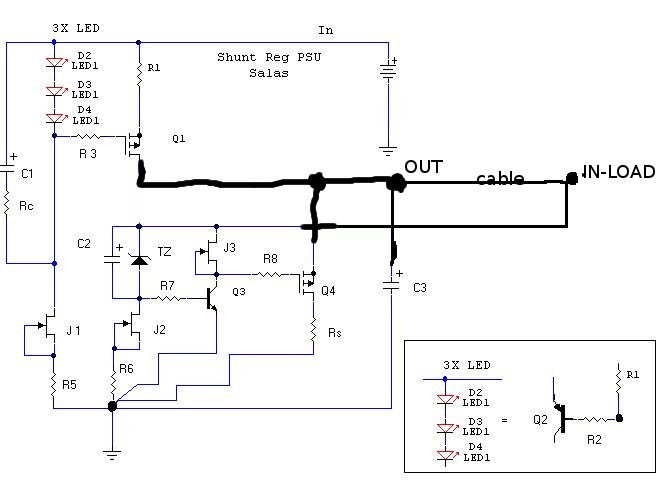
Case 1: all sensing components connected directly to drain of Q1 and source of Q4. 20cm cable connecting source of Q4 to a 80mA DC 30mA AC load.
a) scope showed about 200uV ripple on source of Q4
b) scope showed about 2mV ripple on load
Case 2: disconnected all sensing components from source of Q4 and connected them directly to the load with a separate cable of about 20cm.
a) scope showed about 200uV ripple on load
b) scope showed about 2mV ripple on source of Q4
We're talking about a 20cm wire, not even very thin, soldered on both sides! It would be good if someone else double checked this.
OK, so I just tested my theory with a load of 80mA DC + 30mA AC.
Case 1: all sensing components connected directly to drain of Q1 and source of Q4. 20cm cable connecting source of Q4 to a 80mA DC 30mA AC load.
a) scope showed about 200uV ripple on source of Q4
b) scope showed about 2mV ripple on load
Case 2: disconnected all sensing components from source of Q4 and connected them directly to the load with a separate cable of about 20cm.
a) scope showed about 200uV ripple on load
b) scope showed about 2mV ripple on source of Q4
We're talking about a 20cm wire, not even very thin, soldered on both sides! It would be good if someone else double checked this.
Great work Iko................I wonder if you can hear the difference but every little thing helps and the total sum of all the changes is probably quite audible.
I know that attention to detail like this is quite obvious in the implementation of feedback loops in power amps.
Jam
I know that attention to detail like this is quite obvious in the implementation of feedback loops in power amps.
Jam
Haven't had the time to put on the headphone amp to listen carefully, but I don't think it would make so much of a difference to my setup right now, as I'm using it with a phono stage that doesn't benefit much from low output impedance. It should make a difference though in the gainclone that I'm planning to power with a couple of shunts.
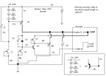
Ah, the remote sense system, like the Super Reg "a la" Jung, Didden, ALW, etc.
So, you have left the R8 close to the Q4, and seperated the +ve connection of the J3, ZD (and it's C2) with a "sense wire" connected seperately to the active cct load point, and it makes a noticeable difference, yes?
Then, the gnd (or 0volt) point should also be seperated too - thus the 0v at R6 and Q3 should also have a "remote sense" seperate wire from the active cct load, yes?
As the pcb layout is based on the idea of "star point", this will require a rather different design, methinks.
Could you try this extra 0volt wire idea, Iko?
I remember well the confusion (and some "disbelief") this little thing produced when the Super Reg was first introduced and the patience of many people explaining the idea of "remote sense".
Interesting, James. I'm a few years behind, as you can see 
I'll look into it then, sure.
Edit: I would leave the star ground as is for now. I'm having a bit of trouble understanding why the ground of the sense should be "moved' to a higher potential. Simulations confirm my suspicion that it would make things worse, but I could be wrong.
I'll look into it then, sure.
Edit: I would leave the star ground as is for now. I'm having a bit of trouble understanding why the ground of the sense should be "moved' to a higher potential. Simulations confirm my suspicion that it would make things worse, but I could be wrong.
Yes, "floating" the 0volt to the R6 shouldn't matter at all, but loosening the solid gnd point of the Q3 could possibly be a problem. Interesting, eh!
Also, if you look at the J3 current source, would this be better "floating" on the sense wire (a feedback mechanism, as you have tried) or would it be better off tied directly to the Q4 source (no f.back &/or possible stability problems?)
This would, maybe, leave only the ZD (and C2) subject to the sense (feedback) correction - simpler to follow, but perhaps not
correct either!
If it's possible with your setup, could you try this out?
Yeah, I come from awhile back when we built the transformers for sound, valve rectifiers, and used snubbers and such things for noise control, etc - it's quite suprising how much of the "ol' ways" are still useful!
Sorry Iko,
I missed your last post
- a "floating driver stage" with a fixed reference (the opposite to my last post) with the "sense" +ve equal to the gnd wire - those external wires are giving the J3, Q3 the appearance of a differential f.back system, eh!
Stabilty, maybe? Although this Reg with it's heavy Ishunt is so solid, I doubt it'll become a problem.
Thank you for providing so much thought, time and effort for this.
Hi Salas, with now 8000uF of filtering before V1 shunt regulator, my Le Pacific RIAA is sounding good to me with very low noise floor working together with a Coral mc transformer. Components used so far has been all generic with nothing exotic.
I only have 1.0uF coupling capacitor on the RIAA and not sure if changing that to 2.2uF will have any benefit to the sound.
I only have 1.0uF coupling capacitor on the RIAA and not sure if changing that to 2.2uF will have any benefit to the sound.
- Status
- This old topic is closed. If you want to reopen this topic, contact a moderator using the "Report Post" button.
- Home
- Amplifiers
- Power Supplies
- The simplistic Salas low voltage shunt regulator