Ah, very nice indeed! Well done James, thank you! 
James, how would somebody print just the silk screen?
Salas, for me, being new to the whole audio thing, I lack the experience you have in voicing various parts, so, I try to help how I can. I don't have a reference system yet to do proper listening experiments, but once I finish a high voltage regulator for the tube headphone amp, then I should be able to do it. I was hoping that people like you, who have trained ears, will at some point try one of the promising versions and reports the findings. But I'm aware that it takes a lot of time and effort to try new circuits, and people are skeptical of new, untried circuits.
Yes, as salas mentioned, check with the diode tester on your dmm the npn.
You may want to hook up a power resistor of about 500ohm and test it that way. Sanity checks:
* voltage between base and emitter pins of the BC550 should be around 0.66V
* voltage between gate and source on each mosfet should be around 4V
* voltage before the series mosfet should be more than 24V in your case, probably 26 and up
* add a small 1ohm, 2ohm, 0.5ohm or similar resistor between the drain of the shunt mosfet and ground, and check the voltage across it, then divide by the value of the resistor, and see what the current through the shunt is
Good luck, let us know how it pans out.
")
None taken. You mean this?
http://passdiy.com/pdf/a40.pdf
on page 9? Wow, 1978!
I like prototyping, no pressure to make it pretty (except when salas asks for pictures )
)
http://passdiy.com/pdf/a40.pdf
on page 9? Wow, 1978!
I like prototyping, no pressure to make it pretty (except when salas asks for pictures
)
Thanks Salas,
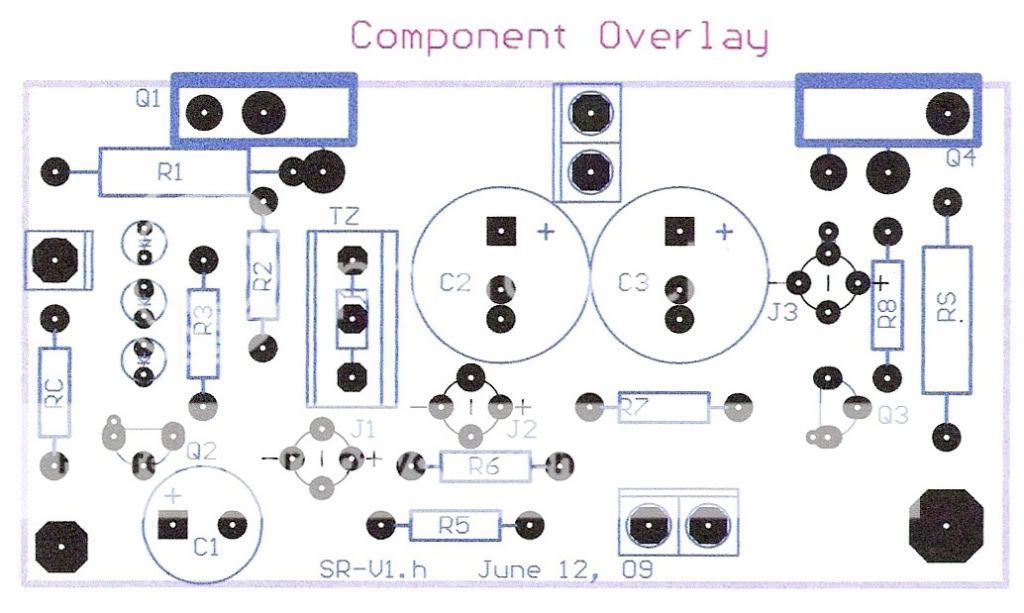
Iko, will this do the trick?
Just print this off after correcting the scale, add on top of the bare perfboard and start pinning the components - the legs of the IRFPs are a bit over 1mm dia so will need pre drilling - same with the "Weidmuller" sockets, but don't really need them unless adjusting the voltages.
I remember a conversation about adding some voltage trimming adjustment, but couldn't find a way without dramatically increasing the Zout, so I just play about with different zeners (and have also tried zeners + reg or green trimming leds in series) and it works just fine.
3k3 calculates for 1.07uV of Johnson noise over 20kHz @ 40 C.
12V Zeners have been found to have about 0.5uV
The resistor noise will be white while the Zener noise will approximate pink.
In my HV shunt I use a resistor Vref driven by a ring of two. Sounds soft. Try it for yourself.
12V Zeners have been found to have about 0.5uV
The resistor noise will be white while the Zener noise will approximate pink.
In my HV shunt I use a resistor Vref driven by a ring of two. Sounds soft. Try it for yourself.
Hi Salas/Iko,
Found the problem...forgot to test it with smoothing caps before the input to the shunt regulator. It is working well already powering my RIAA pre and the noise floor is lower compared to the linear regulator I used earlier.
I used common components for my built. Is there any particular component(s) in the circuit that I could change to make it even better?
Many thanks for the great help.
- Status
- This old topic is closed. If you want to reopen this topic, contact a moderator using the "Report Post" button.
- Home
- Amplifiers
- Power Supplies
- The simplistic Salas low voltage shunt regulator