You describe it subjectively as I have experienced it too. And I too like the Leds better in some applications. For high current I like the Vbe version. A very small difference in the highs is where it focuses in my experience.
I use glass encapsulated 1W 1NxxxxA series. I can't see any brand name on them. My best resolution indirect way of knowing is running FFT for the powered audio circuit and watching the noise floor. Those compensated Zeners have fantastic characteristics, but could not lay my hands on any.
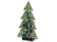
A sure alternative way to stay low is a Leds string for Vref. Especially if making a shunt for the 5-10V region where Zeners are problematic and Leds needed still few. Its like a Christmas tree, better boxed in.
I use glass encapsulated 1W 1NxxxxA series. I can't see any brand name on them. My best resolution indirect way of knowing is running FFT for the powered audio circuit and watching the noise floor. Those compensated Zeners have fantastic characteristics, but could not lay my hands on any.
A sure alternative way to stay low is a Leds string for Vref. Especially if making a shunt for the 5-10V region where Zeners are problematic and Leds needed still few. Its like a Christmas tree, better boxed in.
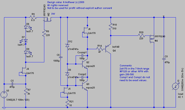
Just an update. I've been working on the prototype and have it working. Not exactly as presented last, made a few changes, but nevertheless working in the real world. Tested it with an AC sine load of about 30mA RMS, on top of a DC load of 80mA. The prototype uses two 11V zeners so the output voltage is about 22.4V. With that load the output voltage had a visible ripple of 200uV. The shunt mosfet was set to about 100mA idle current, which might have been excessive for that load, but whatever. Stable, lower output impedance and wider bandwidth (in simulation). In the real world a proper comparison should be done if anyone cares. The truth is that the promised better performance might not be realizable because of the vagaries of real world circuits with parasitics and blas all over the place. However, maybe with proper layout and top notch components it is possible. At least in theory it is. I will post the actual schematic that is now built a little later. Please don't ask about the sonic merits or lack thereof, because that's not one of my strong points. And sorry for flooding you all so often with so many versions, hopefully I can move on now.
Re: Did someone say Christmas Tree
Imagine the Vref made out of LEDs for the 45V nicoch version of double symmetric (4 pieces on two perfboards). You can listen at night and see around without burning the house lights. Eco friendly.")
jam said:Salas,
This could the new Salas LED Current Source ...........
Imagine the Vref made out of LEDs for the 45V nicoch version of double symmetric (4 pieces on two perfboards). You can listen at night and see around without burning the house lights. Eco friendly.
SOME CLARIFICATION
1) I am not using CFP in my regulators.
2) Jam - I hear your words but did u hear mine ? some people also prefer the SOUND of CFP's - did u ever try them ?
3) I have used them in an amplifier feedback loop without any problems and I enjoyed the sound of that amp very much.
I'm not saying they're the best but I do not think they are inherently evil.
Hi Mike,
I have built several amps. with CFP output stages and some of them worked quite well but were prone to instability driving certain loads especially electrostatics and so I opted for a more traditional approach.
Sometimes under heavy drive conditions ringing used to occur on the tops of waveforms and crossover artifacts become evident but by the same token the amps I design need to be unconditionally stable because of my speskers. In your case they might just fine. The added compensation I need to get them to work usually hurt the sound.
A viable option is the modified CFP that Mr.Nelson Pass used in the Stasis amplifiers, and this is the output stage I plan to use for my next amplifier (which will not use any loop feedback). Thie downside is that it requires a high bias.
Regards,
Jam
P.S. Please post your CFP stage. I would very much like to try it out,
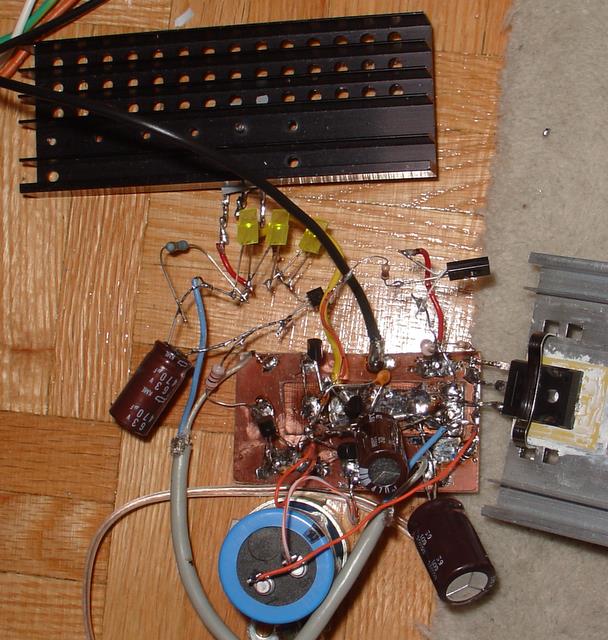
This time I have to agree with Lumba, it's a royal mess!!!  But hey, if it works and it's stable as such an air sculpture, imagine what it should do with proper layout
Here it is, started with a clean board, and it evolved into this mess while trying out all sort of variations, and that is just in the last two days. Below, alive, feeding the salas phono while playing Dire Straits.
Jam, I used two zeners because I needed a point in between to anchor the top transistor in the cascode. Ever since I can see microvolts on the scope I don't worry too much about the noise of the zener. There are plenty of other worries when you get to that level; that's not to say I'm careless when I choose the parts. For instance I could see with my eyes the noise of the zener when it was bypassed with a 10uF cap on the scope, and it was huge. Upped the cap to 1000uF and the noise was gone, just like that.
I don't doubt that using CFPs it's a valid concern. Sometimes though I need to try things out on my own, and see what happens, that's all.
But hey, if it works and it's stable as such an air sculpture, imagine what it should do with proper layout Here it is, started with a clean board, and it evolved into this mess while trying out all sort of variations, and that is just in the last two days. Below, alive, feeding the salas phono while playing Dire Straits.
Jam, I used two zeners because I needed a point in between to anchor the top transistor in the cascode. Ever since I can see microvolts on the scope I don't worry too much about the noise of the zener. There are plenty of other worries when you get to that level; that's not to say I'm careless when I choose the parts. For instance I could see with my eyes the noise of the zener when it was bypassed with a 10uF cap on the scope, and it was huge. Upped the cap to 1000uF and the noise was gone, just like that.
I don't doubt that using CFPs it's a valid concern. Sometimes though I need to try things out on my own, and see what happens, that's all.
Keep going Ikoflexer, I think you could be on the verge of something special.
If it doesn't work first go it is just a matter of trial and error.
"Genius is 1% inspiration and 99% perspiration" Thomas Edison
or maybe this one is more appropriate
"Invention, my dear friends, is 93% perspiration, 6% electricity, 4% evaporation, and 2% butterscotch ripple" Willy Wonka
If it doesn't work first go it is just a matter of trial and error.
"Genius is 1% inspiration and 99% perspiration" Thomas Edison
or maybe this one is more appropriate
"Invention, my dear friends, is 93% perspiration, 6% electricity, 4% evaporation, and 2% butterscotch ripple" Willy Wonka
I had to make some compromises. It's not as good in simulation as the NMOS version that I had high hopes for, but it's stable and it works in practice. Here it is.
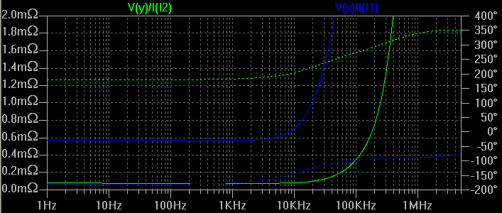
Very simple, but each addition brings something. The cascode and the buffer both lower and extend the bandwidth on the output impedance. It seems to be robust to different parts. I tried a number of NPN drivers, various gains from 200 to 500 and they worked, all just as well. Different than v1, which seems to get an improvement with a higher gain NPN (makes sense). I hope to get rid of the compensation caps by using RF transistors, which I'm waiting for. So it works, and it's stable, I'm listening to it now. Please feel free to comment, if you see anything odd, or if it can be improved somehow.
Output impedance easier to see in db.
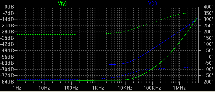
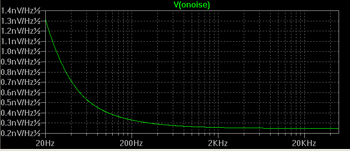
Noise analysis. I don't know how indicative this is, but relative to othe circuits this has lower noise.
Very simple, but each addition brings something. The cascode and the buffer both lower and extend the bandwidth on the output impedance. It seems to be robust to different parts. I tried a number of NPN drivers, various gains from 200 to 500 and they worked, all just as well. Different than v1, which seems to get an improvement with a higher gain NPN (makes sense). I hope to get rid of the compensation caps by using RF transistors, which I'm waiting for. So it works, and it's stable, I'm listening to it now. Please feel free to comment, if you see anything odd, or if it can be improved somehow.
Output impedance easier to see in db.
Noise analysis. I don't know how indicative this is, but relative to othe circuits this has lower noise.
And thank you guys for encouraging me and putting up with my aberrations, it's actually nice to see that someone is actually interested in this. I'm eager to move on for the moment to something else but those results I got earlier, I still hope to get them real one day.
Jam, I probably lost face big time with the photo of the prototype, but hey, what can one do. When you try a hundred things, it can't stay pretty. I've seen many photos of like prototypes from people working for big firms, it's just reality.
Jam, I probably lost face big time with the photo of the prototype, but hey, what can one do. When you try a hundred things, it can't stay pretty. I've seen many photos of like prototypes from people working for big firms, it's just reality.
If you have briefed me to lower the output impedance over an extended bandwidth, that is what I would try. A cascode and a buffer. Seems perfectly logical to me.
The way I develop things up to a point, is that I seek ''adequate'' subjective performance down to an arbitrary threshold that I consider the point of diminishing returns. I try to employ less components possible so to ''voice'' easier, and make easier.
But I also like your approach of seeking the technical edge on a proven basis. If you produce a PCB, I will make one so to examine if the added components skew the tone or just (most probably because they ain't many for the given tech boost) refine it.
Congratulations for your dedication and experiments.
No topological blocks are new, most ideas have been considered before in analogue electronics. Its the dedication and fine taste of the chef that wins the day.
Personally I never claim that a friendly to make, working assortment of components that serves a purpose well is some kind of an original fantastic idea. Mine or anybody's.
You can delete ''salas'' from your cct, its your refinement effort.
First there were electrons.
The clarity of your thinking is what's important, not the rough collection of the components - the spaghetti does what you want and makes perfect sense to you, so how it looks doesn't matter a damn - and often, when you "neaten it up", it doesn't work as well!
It's marvellous that you not only can get the bloody computer SIMs to work so well, but can actually put all the bits together and it works at all!
I reckon you can take a big thank you from all of us for all your efforts.
It's marvellous that you not only can get the bloody computer SIMs to work so well, but can actually put all the bits together and it works at all!
I reckon you can take a big thank you from all of us for all your efforts.
We also need to thank James for his PCB efforts. 
Here is his latest refinement for V1. He has included every possible nut n' bolt. LEDs CCS, Vbe CCS, positive / negative shunt, Zener socket for changing Vout in a sec, clean, compact, star layout. I did not see anything wrong by looking at it, you may have your second look too. James is more suitable to comment on the options and how to implement them I guess. He has also made a few V1s (not in WWII) and maybe he can convey his experiences and applications if he likes to.
Thanks again for your contribution James.
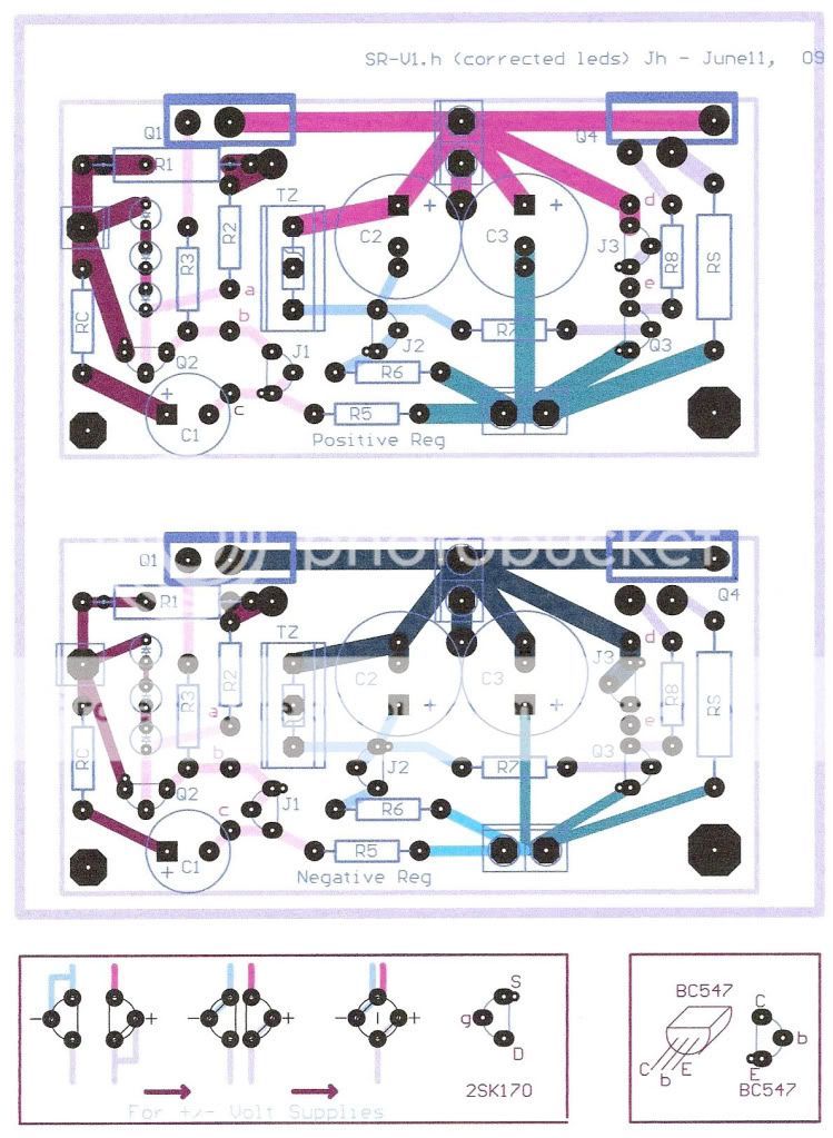
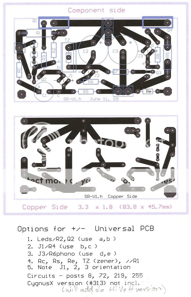
- Status
- This old topic is closed. If you want to reopen this topic, contact a moderator using the "Report Post" button.
- Home
- Amplifiers
- Power Supplies
- The simplistic Salas low voltage shunt regulator