Re: OT
100mm of 0.05mm diameter copper is OK for signal.nicoch46 said:you thinks 10cm 0.5mm Ag is to small for signal ,driver->pw stage?
Hi Salas and all,
I was off the theme 'shunt reg' for some time, I'm back now and am very pleased with what you did! James, your routing is extraordinary! Supershort paths and elegance whereever you look. I will immediatly copy it for my p2p efforts.
One very worthful advantage of such a 'simple' low-parts count regulator is, you can place it close to the load and you can build several of them for a given circuit.
thanks,
Rüdiger
jameshillj said:Found an error on the boards - the leds are supposed to be connected to the input rail, not to the midpoint of R1 and Q1 (I've put them as an alternative for R2 and this is incorrect).
Will fix.
OK, send them to me when ready and I will exchange them.
Onvinyl said:Hi Salas and all,
I was off the theme 'shunt reg' for some time, I'm back now and am very pleased with what you did! James, your routing is extraordinary! Supershort paths and elegance whereever you look. I will immediatly copy it for my p2p efforts.
One very worthful advantage of such a 'simple' low-parts count regulator is, you can place it close to the load and you can build several of them for a given circuit.
thanks,
Rüdiger
Yes, very practical. Keep in mind that the very low output impedance blends stages and channels less, so you may use not that many, especially when utilizing local RC decoupling on your circuits.
Salas said:
Keep in mind that the very low output impedance blends stages and channels less, so you may use not that many, especially when utilizing local RC decoupling on your circuits.
My guess is, with this low output-impedance the impedance of the wiring from reg to the load(s) will dominate the picture.
Do we really need RC-coupling if we star-wire not only the grounds, but the V+/V- lines as well? Doesn't RC-coupling kill the super low impedance from the viewpoint of the load?
Rüdiger
Yeah Rudi,
I've seen some of your designs and posts - I'd guess this sort of cct would make you smile a bit - simple and it works!
I like simple ccts, myself - they match the simple brain here!
The corrected layout is a bit different and adding a few mm for larger tracks/ donuts/ options - a few days.
The dual version with included CMx is coming together rather nicely - having trouble sourcing the right fets for the CT rectifier sytem - on hold for
Working out the testing "protocols" and it looks like a plug in Module to change the diode string for the R2/ Q2 option - we already have a zener plug/socket for different voltages - the change in the R1 for different currents is a pain - haven't sorted that one yet.
Another concern was using the same heatsink for different current/voltages that may "skew" the results a bit, as the component temp changes. I wouldn't mind another opinion about this .....
Currently, I'm thinking about these tests - advice requested.
* +15v @ Icc of 90ma (both Leds and R2/Q2 versions - load of 10ma and 40ma - have the cct values)
* +15V @ Icc - 250ma (load 10ma and 100ma - have cct values)
* +24v @ Icc - 550ma ( load 250ma, for my headamp!)
* + 44v @ 200ma (the Cygnus X version - Naim front end).
Tests to have input ripple 50mv (maybe sawtooth, not sine).
Depending on the time available, testing for the usual impedance/freq, residual ripple/freq on output, step function (perhaps that test cct) - if it's similar to Iko's SIM tests, can compare these results.
Than mentioned using a sawtooth input (ripple) instead of the usual sine - I think it's a more relevant test but, it will probably give different results - again, advice requested.
I haven't confirmed just how much time is available yet so much of this may not be possible - however, just planning stage for this.
Onvinyl said:
My guess is, with this low output-impedance the impedance of the wiring from reg to the load(s) will dominate the picture.
Do we really need RC-coupling if we star-wire not only the grounds, but the V+/V- lines as well? Doesn't RC-coupling kill the super low impedance from the viewpoint of the load?
Rüdiger
Given that you use short and thick star wiring both for +V and earth (have tested this, its audibly better for dynamics and resolution), the local decoupling strategy has more to do with the PSRR of the most sensitive stages. Its mostly dependent on using a big low ESR cap locally if needed, and the current draw of stages supplied commonly. Not a straightforward answer. I determine the effectiveness of local decoupling by running FFT and watching the noise floor under 500Hz, with and without it. If its negligible, I avoid it. Also, under a threshold, I don't think that we listen directly to the interaction of impedance, but if some characteristics are excellent in a reg, its an indication of its unflappability under complex interactions with stages and thick musical signals, that is audible in the end. I use dense choral music with full tilt orchestra to examine such. Like Mythodea.
high bandwidth and stability
In the last little while there were several shunt regulator designs being worked on and I've seen people mention stability, but not many details about it. So lately I've been analyzing the stability of v1 and v2c, these two versions being the only two I am really interested at the moment. All analysis was done on the simulator. For v1 (R6 mod, LED bias) it seems that the circuit as is happens to be at the edge of stability. The calculated phase margin at unity gain was about 1 degree; to be somewhat sure that the circuit is stable (taking real world environment and component variations) designers try to get a phase margin of about 45 degrees. My personal experience was that there were times when I built v1 and it worked right away, stable, and then there were times when it oscillated, so the simulated stability analysis is in some correlation to reality. Considering various differences between components in the real world, this would happen. An significant increase in phase margin can be had by a small capacitor on C-B pins of the NPN driver transistor. In simulation an 18pF capacitor would bring the phase margin to 35 degree. This does not mean that you should use this value. I would take this result to mean that, all else being equal, if you build v1 and it oscillates, the first thing to try would be a small cap on the C-B pins of the BC550B. I would step up the value if still oscillating, up to about 300pF. If it still oscillates then it almost surely a different problem.
All the simulated outstanding output impedance results I have shown so far for v2c (the two stage amplifier with a cascode in the first stage) are without a significant frequency compensation. The results would look a bit less stellar with compensation. This is a very funny game played here, the more loop gain you have across the frequency spectrum, the more inherently unstable the circuit will become (the phase lags at high frequency and you get into negative phase margin). When you try to compensate (various ways) the loop gain decreases at high frequency and behold, the output impedance goes down big time. I realized that in order to maintain high loop gain AND stability one should be serious about wide bandwidth design. As far as I am concerned, for v2c, to make it keep its lower than v1 output impedance I could use bfrt92 and bfrp92 RF drivers with high frequency compensation (details left out). Is it worth it? For those who want to squeeze the very last bit of performance out of a circuit, perhaps. For most, you can be pretty sure that most people will not be able to do better then salas version 1. Am I 100% positive of all this? Nope. Please correct me if I'm wrong.
Any high speed amp designers around here to give some advice?
Salas said:V1 has been made very many times since fall 2008 by many different people in different guises. It worked in all cases. Always with a Cout on board in the hundreds of uF.
Then my analysis must be wrong. As long as it worked for people, I have no problem being wrong.
Its not necessarily wrong. The current source as a load brings the gm*load gain pretty high. I was worried for instability issues my self when we did that mod in the Riaa thread. In practice it worked for all people with gains in the highs, so no worries. The real components seem they can give a somewhat more margin than predicted, so if it works, its better to keep the gain up high. In a case (not reported yet) that there is persistent instability, the npn can be BC550B instead of C for instance, so to compromise the loop gain. Or use a comp cap between C,B of the driver, as you saw. Stacked ceramic I would suppose.
higher speed version
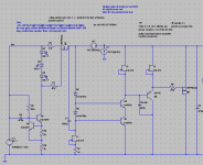
My idea is to use smaller mosfets unless u really need to use big ones.
The version of the cct I posted here used zvp3306a's
perhaps for low current & low voltage applications this would be ok
http://www.diyaudio.com/forums/showthread.php?postid=1825993#post1825993
I think this would be faster
but might be wrong
just my idea")
My idea is to use smaller mosfets unless u really need to use big ones.
The version of the cct I posted here used zvp3306a's
perhaps for low current & low voltage applications this would be ok
http://www.diyaudio.com/forums/showthread.php?postid=1825993#post1825993
I think this would be faster
but might be wrong
just my idea
- Status
- This old topic is closed. If you want to reopen this topic, contact a moderator using the "Report Post" button.
- Home
- Amplifiers
- Power Supplies
- The simplistic Salas low voltage shunt regulator