Maybe I should also try MPSA18 .... I have some...
Ricardo
Ricardo, you should definitely give it a try. But with those miles of shunt output cables you got there... I'm not sure it can make a difference

 (just kidding)
Attachments
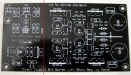
There's the pcb part of the buffer GB, which includes some variation of v1, but I haven't checked the schematic out, salas, maybe you can say something about it.
I'm working on a pcb for v1.5 and v2, have been prototyping heavily for the last two weeks. It's still under construction though. Got some nice results so far. However, these circuits are not very difficult to build, even point to point.
I'm working on a pcb for v1.5 and v2, have been prototyping heavily for the last two weeks. It's still under construction though. Got some nice results so far. However, these circuits are not very difficult to build, even point to point.
Attachments

There's the pcb part of the buffer GB, which includes some variation of v1, but I haven't checked the schematic out, salas, maybe you can say something about it.
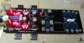
Its led referenced 10V symmetrics with 100uF output caps set at 70mA CCS for the DC B1. at such voltages leds are lending themselves bcs you can reach with just 5. Guys who have AC coupled original B1, made DC with 317 & 337 and then that. They had a large benefit as they said. Still B1 is a CCSed line level follower and is supposed to be more immune than an SE resistor loaded phono for instance. The output caps I chose are for good termination given the vrefs, CCS settings, etc. Taking into account typical layout ''sins''. So to get good step response as JWB once measured an excellent result. Kinda optimized you could say.
Someone can take part in the GB, get one, cut along the red line. Can mount the IRFPs under PCB to a thick enough metal floor. No sinks for 200-300mA per side. Just a silicone insulation pad.
If for higher Vout, can get creative with all those led pads for Vref. Good zeners, resistors, since there is already an inline ccs, whatever.
Attachments
Hi Guys,
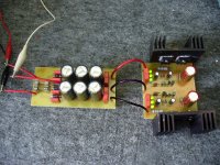
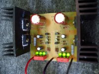
this is my negative and positive Salas shunt regulator but the only difference i use irfp150 and irfp9140 for mosfets. i will test as soon as possible in preamp line stage. Some picture. Thanks Maxpou
this is my negative and positive Salas shunt regulator but the only difference i use irfp150 and irfp9140 for mosfets. i will test as soon as possible in preamp line stage. Some picture. Thanks Maxpou
Attachments
Clean job maxpou,
Noticed you use bypass caps on the diodes. This was formerly done with junction diodes like 4007 to lower the current overshoot. With modern, fast diodes it's better to leave them off to allow for fast recovery. Ringing would be less without bypass caps.
Noticed you use bypass caps on the diodes. This was formerly done with junction diodes like 4007 to lower the current overshoot. With modern, fast diodes it's better to leave them off to allow for fast recovery. Ringing would be less without bypass caps.
Clean job maxpou,
Noticed you use bypass caps on the diodes. This was formerly done with junction diodes like 4007 to lower the current overshoot. With modern, fast diodes it's better to leave them off to allow for fast recovery. Ringing would be less without bypass caps.
Apreciated this comment. Thanks.
Ricardo
What about contributing the pcb? Looks practical.
Thanks Salas for comment but i don't understand this question. sorry for my english. maxpou
Clean job maxpou,
Noticed you use bypass caps on the diodes. This was formerly done with junction diodes like 4007 to lower the current overshoot. With modern, fast diodes it's better to leave them off to allow for fast recovery. Ringing would be less without bypass caps.
Thank you disco, but i use the BY255 for my diodes. Maxpou
Finished shortening and doubling the hot wires between shunts and riaas, and there seemed to be an inprovement in the bass but sound became somehow muddled. Do not know if using double cables does this.
After that I shortened the gnd wires from the riaa. (Inittially all gnd wires went to a central star gnd. Now I wired the riaa gnd to the shunts and these to star gnd).
This mod gave very noticeable improvements in bass definition and overall stereo image stability.
Maybe I should double the gnd wires between riaa and shunts also ...
Ricardo
PS: All gnd and hot wires have the same lenght now.
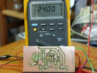
Basic question coming up - I sat down to measure my 2SK170GR's IDSS to get the high ones for use in this reg - As my Fluke 16 DMM max current is 200uA I used the technique of: short the gate to the source and add a 9V battery from the drain to the source & I put a 100 ohm resistor between the drain and the battery and measure across it so 0.1V=1mA, I think. So far, so good but something is amiss - when I measure about 50 of these GRs I get a range from 0.29V to 1.61V which would make them in the IDSS current range of 2.9mA to 16mA. This couldn't be, could it? - the GR range is 2.6mA to 6.5mA
Edit: 9V battery was down at 8.6V but i don't think this matters, does it?
Edit: Just double checking - looking at the SK170 from the bottom - pin 1 (drain) is on the left, correct?
Edit: 9V battery was down at 8.6V but i don't think this matters, does it?
Edit: Just double checking - looking at the SK170 from the bottom - pin 1 (drain) is on the left, correct?
Last edited:
Finished shortening and doubling the hot wires between shunts and riaas, and there seemed to be an inprovement in the bass but sound became somehow muddled. Do not know if using double cables does this.
After that I shortened the gnd wires from the riaa. (Inittially all gnd wires went to a central star gnd. Now I wired the riaa gnd to the shunts and these to star gnd).
This mod gave very noticeable improvements in bass definition and overall stereo image stability.
Maybe I should double the gnd wires between riaa and shunts also ...
It's easy to try, why not.
- Status
- This old topic is closed. If you want to reopen this topic, contact a moderator using the "Report Post" button.
- Home
- Amplifiers
- Power Supplies
- The simplistic Salas low voltage shunt regulator